
Page 306 - Softbound_Edition_19_en
P. 306
Spool valve
Spool valve Spool valve
TYPE CODE PERFORMANCE SPECIFICATIONS
2
WF F F A06 - - - # Oil viscosity u = 30 mm /s
Spool valve, direct operated Δp = f (Q) Pressure drop-volume flow characteristics Volume flow direction
Hydraulically actuated ∆p [bar] Symbol P - A P - B P - T A - T B - T
25 K4256 1 AB1 / AB2 2 2 - 3 3
Flange construction 2
20 3 AB3 1 1 - 2 2
International standard interface ISO, NG6 15 4 ACB 2 2 - 3 3
10 ADB 2 2 - 4 4
Designation of symbols acc. to table
5
Pilot oil sideways se 0
via mounting interface ae 0 10 20 30 40 50 60 70 80 Q [l/min]
Sealing material NBR
FKM (Viton) D1 DIMENSIONS
NBR 872 y-Z604
9.5
Design index (subject to change) 5.2 MD=60Nm15 15 MD=60Nm
MD= 5.2Nm
1.7-32
8
HYDRAULIC SPECIFICATIONS STANDARDS 49 G1/4"
41
Working pressure p = 350 bar Mounting interface ISO 4401-03-03 23.5
max
Tank pressure p T max = 200 bar Contamination ISO 4406 50 60
Resp. 15 bar lower than the control efficiency MD=60Nm 10 50 60 10 MD=60Nm 46 30.1 68 30.1
pressure 12.6 68 12.6 128.2
93.2
Maximum volume flow Q = 80 l/min, see characteristics
max ACCESSORIES
Leakage oil See characteristics
Fluid Mineral oil, other fluid on request Fixing screws Data sheet 1.0-60 HYDRAULIC CONNECTION PARTS LIST
Viscosity range 12 mm /s…320 mm /s Threaded subplates Data sheet 2.9-30 Position Article Description
2
2
Temperature range -25…+70 °C (NBR) Multi-station subplates Data sheet 2.9-60 17.8 10 239.2210 Socket head screw M20 x 1
fluid -20…+70 °C (FKM) Horizontal mounting blocks Data sheet 2.9-100 T 6.5
Contamination Class 20 / 18 / 14 Technical explanations Data sheet 1.0-100 6.5 15 032.4818 Bush rd 24 / M3 x 38,5
efficiency 31 x A B y 21 32.5 251.2225 Seal kit
Filtration Required filtration grade ß 10…16 ≥ 75, Filtration Data sheet 1.0-50
see data sheet 1.0-50 P Seal kit consisting of
21.5 50 O-Ring ID 9,25 x 1,78
40.5 60 O-Ring ID 5,28 x 1,78
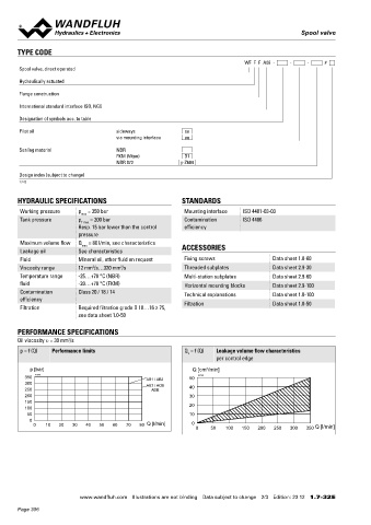
PERFORMANCE SPECIFICATIONS
Oil viscosity u = 30 mm /s
2
p = f (Q) Performance limits Q = f (Q) Leakage volume flow characteristics
L
per control edge INSTALLATION NOTES SURFACE TREATMENT
p [bar] Q [cm /min] Mounting type Flange mounting The valve body, the screw plug and the bush are zinc-nickel coated
3
350 K4257 AB1 / AB2 50 K4258 4 fixing holes for
300 AB3 / ACB socket head screws M5 x 50 ISO 9227 (800 h) salt spray test
250 ADB 40
200 30 Mounting position Any, preferably horizontal
150 20 Tightening torque Fixing screws M = 5,2 Nm (screw
D
100 quality 8.8, zinc coated)
50 10
0 Note! The length of the fixing screw depends on the base
0 10 20 30 40 50 60 70 80 Q [l/min] 0 Q [l/min]
0 50 100 150 200 250 300 350 material of the connection element.
SEALING MATERIAL
NBR or FKM (Viton) as standard, choice in the type code
Wandfluh AG Postfach CH-3714 Frutigen
Tel. +41 33 672 72 72 Fax +41 33 672 72 12 sales@wandfluh.com
www.wandfluh.com Illustrations are not binding Data subject to change 2/3 Edition: 23 12 1.7-32 E www.wandfluh.com Illustrations are not binding Data subject to change 3/3 Edition: 23 12 1.7-32 E
Page 306