
Page 242 - Softbound_Edition_19_en
P. 242
Solenoid operated spool valve
Solenoid operated spool valve Solenoid operated spool valve
PERFORMANCE SPECIFICATIONS DIMENSIONS
Oil viscosity u = 30 mm /s 4/3-way valve (spring centred) 4/2-way valve (spring reset)
2
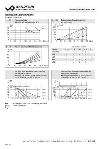
p = f (Q) Performance limits Q = f (Q) Leakage volume flow characteristics A X B A 130 140 E MD= 10.5Nm (8.8)
L
Measured with nominal voltage -10 % per control edge 13.5Nm (10.9)
3
p [bar] Q [cm /min] 104.5
350 K4109 AFB / BEA 250 K4111 64 70
300 ADB / ACB 200 W =
250 AB1 / AB2 29
200 150 10
150 100 70 60 10 50 6.5
100 307 MD=5Nm 11.5
50 50 HF1 HS1 35 72 93.2 14.1
0 0 64.9 71.4 214.3
0 20 40 60 80 100 120 Q [l/min] 0 50 100 150 200 250 300 350 p [bar] 51.4 51.4
80 30
Δp = f (Q) Pressure drop volume flow characteristics Volume flow direction 90 A
p [bar] Symbol P - A P - B P - T A -T B - T
20 K4110 1 AB1 / AB2 4 4 - 2 1 105.8
2 X 60 76
15 3 ACB 5 5 - 4 3 M =
4 *
10 5 ADB 5 5 - 4 3
6 BEA 5 5 3 5 4 10
5 7 68
AFB 6 6 7 7 7
0 35 72
0 20 40 60 80 100 120 Q [l/min] 214.3
*optionally spindle E = Air bleed screw
Orifices in valve body influence the switching times
Switching times, influence of the soft switching Switching times, influence of the soft switching
Switching on the solenoid Switching off the solenoid
Measured with WWMFA10-ACB-G24 in comparison Measured with WWMFA10-ACB-G24 compared
with WDMFA10-ACB-G24 at Q = 90 l/min with WDMFA10-ACB-G24 at Q = 90 l/min HYDRAULIC CONNECTION PARTS LIST
U [V] U [V] Position Article Description
24 24 54 10 206.3… W.E64 / 31 x 72
0 0 P 260.9… M.S60 / 31 x 72
p [bar] WDMFA10-ACB (stark systemabhängig) p [bar] WDMFA10-ACB (stark systemabhängig)
300 E K4112 300 E K4113 1.5 16.8 50 160.2120 O-ring ID 12,42 x 1,78 (NBR)
250 Düse 0,8 250 Düse 0,8 46 A B 9.7 160.8124 O-ring ID 12,42 x 1,78 (FKM)
200 200
150 Düse 0,5 150 Düse 0,3 T To 60 160.2282 O-ring ID 28.24 x 2.62 (NBR)
100 100 70 154.2706 Knurled nut
50 Düse 0,3 50 Düse 0,5 20.8
0 0 80 253.7006 HF1-M24
0 0.1 0.2 0.3 0.4 0.5 0.6 0.7 0.8 0.9 1 t [s] 0 0.1 0.2 0.3 0.4 0.5 0.6 0.7 0.8 0.9 1 t [s] 24
90 253.7005 HS1-M24
Note! With the option spindle «S», the switching time can be 130 246.3006 Socket head screw M6 x 20 DIN 912
adjusted individually. 140 049.2062 Bonded seal ID 4,1 x 7,2 x 1
Wandfluh AG Postfach CH-3714 Frutigen
Tel. +41 33 672 72 72 Fax +41 33 672 72 12 sales@wandfluh.com
www.wandfluh.com Illustrations are not binding Data subject to change 4/5 Edition: 22 09 1.4-42 E www.wandfluh.com Illustrations are not binding Data subject to change 5/5 Edition: 22 09 1.4-42 E
Page 242