Page 1220 - Softbound_Edition_19_en
P. 1220

Proportional throttle valve                                                                                                  Proportional throttle valve
                                                                                    Proportional throttle valve


       PERFORMANCE SPECIFICATIONS                                                                                                  DIMENSIONS
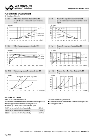
       Oil viscosity u = 30 mm /s                                                                                                  With analog interface, 12 pole connector             With analog interface, 7 pole connector
                       2
                                                                                                                                   Amplifier and controller                             Amplifier and controller
       Q = f (I)  Volume flow adjustment characteristics DN  Q = f (I)  Volume flow adjustment characteristics DO
                  p1 - p2 = 20 bar / s corresponds to command value   p1 - p2 = 20 bar / s corresponds to command value                              25,30  20,21    40                                  X2
                  signal                                              signal
                                                                                                                                                              X2
          Q [l/min]                                            Q [l/min]                                                                                                                           X1
         35  K1141                                            35  K1167                                                                                 X1
         30                                    Q = 25 l/min   30         Q = 25 l/min
                                                N
                                                                          N
         25                                                   25                                                                                        X4              s30               118.4    X4
         20                                                   20   Q = 10 l/min                                                       100.4      15                        M22x1.5
         15                                    Q = 10 l/min   15    N                                                                         MD=5.5Nm                       (2)
                                                N
         10                                    Q = 6,3 l/min  10                                                                                                                 (1)
                                                N
          5                                                    5   Q = 6,3 l/min                                                        35                                                 35
                                                                    N
          0                                                  0                              
            0   10  20  30  40 50 60 70 80 90  100 s [%]        0   10  20  30  40 50 60 70 80 90  100 s [%]
                                                                                                                                                 12    17          18     50  60  70    X4 (controller only)
                                                                                                                                              MD=5Nm           91.3
                                                                                                                                                              107.9
       Q = f (p)  Volume flow pressure characteristics DN   Q = f (p)  Volume flow pressure characteristics DO
                                                                                                                                                         148.3               37.5
                  I = I                                               I = I
                    G                                                    G                                                                                   185.8
          Q [l/min]                                            Q [l/min]
         35  K0205_1                                          45  K1166                                                            With fieldbus interface                              With fieldbus interface
         30                                     Q = 6.3 l/min  40                                    = 25 l/min                    Amplifier                                            Controller
                                                              35
                                                 N
         25                                     Q = 10 l/min  30                                   Q N
                                                 N
         20                                     Q = 25 l/min  25                                   Q N  = 10 l/min                                       X2                                              X2
         15                                      N            20                                                                                                                                  X1
                                                                                                    N
         10                                                   15                                   Q = 6,3 l/min                                  X1
                                                              10
          5                                                    5
          0                                                    0                                                                                  X3                                              X3
            0   50  100  150  200  250  300  350 p [bar]        0    50  100  150  200  250  300  350 p [bar]                         100.4                                               118.4
                                                                                                                                                                                                  X4
       ∆p = f (Q)  Pressure drop volume flow characteristic DN  ∆p = f (Q)  Pressure drop volume flow characteristic DO                  35
                  I = I                                               I = I
                    G                                                    G                                                                                                                 35
           p [bar]                                             p [bar]
                                                                           N
                                        N
                                                                                    N
                      N
                               N
         40  K1163    Q = 6,3 l/min  Q = 10 l/min  Q = 25 l/min  50  K1164  Q = 6,3 l/min  Q = 10/min
         30                                                   40
                                                              30
         20                                                                                        Q = 25 l/min
                                                                                                    N
                                                              20                                                                   HYDRAULIC CONNECTION                                 PARTS LIST
         10                                                   10                                                                   Cavity drawing according to ISO 7789–22–01–0–98       Position Article  Description

          0                                                    0                                                                                                                              12 154.2700  Knurled nut
            0    5   10   15   20   25  30   35  Q [l/min]      0    5    10   15  20   25   30   35  Q [l/min]                                          M22x1.5
                                                                                                                                                                                              15 253.8000  Manual override HB4,5

                                                                                                                                                                                              17 160.2187  O-ring ID 18,72 x 2,62 (NBR)
       FACTORY SETTINGS                                                                                                                                           (2)                         18 160.2170  O-ring ID 17,17 x 1,78 (NBR)
       Dither set for optimum hysteresis DN                Dither set for optimum hysteresis DO                                                                                               20 223.1317  Dummy plug M16 x 1,5
       ◆ = Deadband: solenoid switched off at command value signal < 5 %  ◆ = Deadband: solenoid switched off at command value signal < 5 %                       (1)                         21 160.6131  O-ring ID 13,00 x 1,5 (FKM)
       ● = Opening pressure at command value signal + 10 %  ● = Closing point at 90 %                                                                                                         25 062.0102  Cover
       ■ = Flow at ∆p = 30 bar at 70% command value signal                                                                                                                                    30 072.0021  Gasket 33,2 x 59,9 x 2
                                                                                                                                                          (1)
       15,0 l/min  at nominal volume flow rate Q  25 l/min
                                     N                                                                                                                                                        40 208.0100  Socket head screw M4 x 10
       10,0 l/min  at nominal volume flow rate Q N  10 l/min                                                                       Note!    For detailed cavity drawing and cavity tools see data   50 160.2188  O-ring ID 18,77 x 1,78 (NBR)
       5,2 l/min  at nominal volume flow rate Q  6,3 l/min                                                                                  sheet 2.13-1008                                      160.6188  O-ring ID 18,77 x 1,78 (FKM)
                                     N
                                                                                                                                                                                              60 160.2156  O-ring ID 15,60 x 1,78 (NBR)
                                                                                                                                                                                                 160.6156  O-ring ID 15,60 x 1,78 (FKM)
                                                                                                                                                                                              70 049.3196  Backup ring rd 16,1 x 19 x 1,4


                         www.wandfluh.com  Illustrations are not binding  Data subject to change  4/6  Edition: 22 46  2.6-541 E                      www.wandfluh.com  Illustrations are not binding  Data subject to change  5/6  Edition: 22 46  2.6-541 E
       Page 1220
   1215   1216   1217   1218   1219   1220   1221   1222   1223   1224   1225