Page 1192 - Softbound_Edition_19_en
P. 1192

48
                                                10,5
                                                  6,5
                                                Ø
                                                  Ø
                                                                                           54
                                                            53
                                                    7 )
                                                   (
                                                                                           105
                                                6,5
                                                Ø
                                                                                        (120)
                                                           35 60 35  10  *  30  46  9,7  16,8  1,5  46  20,8  50  *  30  60  60
                                                         60                                 170
                                                                                           Flow control valve
                                                                                          Flow control valves                                                                                               Pressure compensating valves
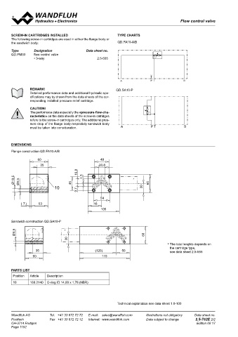
       SCREw-IN CARTRIDGES INSTALLED                        TYPE CHARTS                                                            Pressure compensating valve
       The following screw-in cartridges are used in either the flange body or                                                     Sandwich construction
       the sandwich body:                                   QD.FA10-A/B                                                                                                                     ®
                                                                                                                                   • 2-way operation                            NG4-Mini
       Type       Designation               Data sheet no.                                                                         • Q max  = 10 l/min
       QD.PM33    flow control valve                                                                                               • p    = 315 bar
                  • 3-way                         2.5-555                                                                             max
                                                                                                                                   DESCRIPTION                        FUNCTION                           APPLICATION
                                                                                                                                   Pressure compensator valve with fixed setting   The pressure compensator valve maintains a   Pressure compensator sandwich valves are
                                                                                                                                   in sandwich design with interface NG4-Mini   constant differential pressure through an orifice   usually stacked underneath proportional di-
                                                             A              P T              B                                     acc. to Wandfluh standard with 4 ports. The   (e.g. metering edge of a directional valve). The   rectional valves. They are used in open loop
                                                                                                                                   steel body of the sandwich valve is phospha-  2-way  pressure  compensator  restricts  the   circuits. 2-way pressure compensators may
                REMARK!                                    QD.SA10-P                                                               tized and the cartridge body is zinc coated for   volume flow in the meter-in mode.  be installed in parallel pressure lines with a
                Detailed performance data and additional hydraulic spe-                                                            corrosion  protection.  The  load  is  sensed  in                     common power source to operate actuators
                cifications may by drawn from the data sheets of the cor-                                                          line A or B with an incorporated shuttle valve.                       individually. For each actuator the full pump
                responding installed pressure relief cartridge.                                                                                                                                          pressure is available.
                CAUTION!
                The performace data especially the «pressure-flow-cha-
                racteristic» on the data sheets of the screw-in catridges
                refere to the screw-in cartridges only. The additional pres-                                                                                          TYPE CODE
                sure drop of the flange body respectivly sandwich body
                must be taken into consideration.            A               P T             B                                                                                                                         U  Z   F   S  A04  #

                                                                                                                                                                      Pressure compensator, 2-way
       DIMENSIONS                                                                                                                                                     Type of adjustment   fixed setting

       Flange construction QD.FA10-A/B                                                                                                                                Sandwich construction
                    60                             48                                                                                                                 Mounting interface acc. to Wandfluh standard, NG4-Mini
                     35                            20,8                                                                                                               Design-Index (Subject to change)
                                        16,8
        10,5  6,5                         1,5                       *
        Ø  Ø                         46                                     60                                                      20         Ø 5.5
                            10                                          30
                                       9,7
                                                                                                                                   GENERAL SPECIFICATIONS                      UZFSA04  HYDRAULIC SPECIFICATIONS
                                                   54                                                                              Designation       2-way pressure compensating valve  Hydraulic fluid      Mineral oils, other media on request
                                                                                                                                      40
           (  7 )   53                          46                                                                                 Size              NG4-Mini acc. to Wandfluh standard  Max. permissible    ISO 4406:1999, class 18/16/13
                                                                                                                                   Construction      Sandwich construction              contamination level   (Recommended filter gauge ß6...10≥75)
                                                                                                                                                                                 16
                                                                                                                                                                               24
                                                   105                                                                             Mounting          3 mounting holes for M5 socket head screws              see data sheet 1.0-50/2
                                                                                                                                                     or M5 locking screws               Viscosity range      12 mm /s ... 320 mm /s
                                                                                                                                                                                                                  2
                                                                                                                                                                                                                           2
                                                                                                                                   Type of connection   Thread connection plates        Hydraulic fluid temperature  -20 ...+70 °C
                                                                                                                                              10
                                                                                                                                                                          14.2
                                                                                                                                                         110
       Sandwich construction QD.SA10-P                                                                                                4.2            Rows of flange plates and horizontal  Peak pressure     p max   = 315 bar
                                                                                                                                              27     stacking system                    Differential pressure   p Diff.   = 10 bar
        6,5                      *                                                                                                 Ambient temperature   -20…+50 °C                       Maximum volume flow   other differential pressures on request
                                                                                                                                                     any
                                                                                                                                                                                                                = 10 l/min
                                                                                                                                                                                                             Q
                                                                                                                                   Installation position
                                                                                                                                                                                                              max
        Ø                                                                60                                                        Fastening torque   M  =  5,5 Nm (Qual. 8.8) for fixing screws  Leakage volume flow   see characteritics
                                                                                                                                                      D
                                   30                                                                                                             P  M  = 50 Nm for screw cartridge
                                                                                                                                                      D
                                                                                     *  The total lenghts depends on               40  Weight   A    m = 1,5 kg
                                                                                                                                                     B
                                                                                       the cartridge type,                            14    T          T0
                   35                            (120)        50                       see data sheet 2.5-555                                                                   24
                 60                                 170
                                                                                                                                   SWITCHING DIAGRAMS                                   MECHANICAL ACTUATION
                                                                                                                                                 14
                                                                                                                                                 28                                     Fixed setting design. Other differential pressures available on
       PARTS LIST                                                                                                                  2-way operation                                      request.
        Position  Article  Description
        10      160.2140  O-ring ID 14,00 x 1,78 (NBR)
                                                                                                                                    A       P T       B        A       P T      B
                                                            Technical explanation see data sheet 1.0-100
       Wandfluh AG        Tel.  +41 33 672 72 72   E-mail:  sales@wandfluh.com   Illustrations not obligatory   Data sheet no.     Wandfluh AG         Tel.  +41 33 672 72 72   E-mail:  sales@wandfluh.com   Illustrations not obligatory   Data sheet no.
       Postfach           Fax  +41 33 672 72 12   Internet:  www.wandfluh.com   Data subject to change   2.5-762E 2/2              Postfach            Fax  +41 33 672 72 12   Internet:  www.wandfluh.com   Data subject to change   2.5-820E 1/2
       CH-3714 Frutigen  A           P T             B                                             Edition 08 17                   CH-3714 Frutigen                                                                             Edition 21 33
       Page 1192


                      A              P T             B
   1187   1188   1189   1190   1191   1192   1193   1194   1195   1196   1197