Page 1104 - Softbound_Edition_19_en
P. 1104

Proportional
                                                                         Proportional pressure reducing valve                                                                                          Proportional pressure reducing valve
                                                                                     pressure reducing valves

                                                                                                                                   Proportional pressure reducing valve
       SCREw-IN CaRTRIDGES INSTallED
       The following screw-in cartridges are used in either the flange body or the sandwich   REMaRK!                              Flange construction                                  NG4-Mini
       body:                                                                Detailed performance data and additional hy-                                                                Wandfluh standard
       Type         Designation               Data sheet no.   Q max *      draulic and electric specifications may by drawn        ◆  direct operated
       MVPPM22      pilot operated                2.3-629   20 l/min        from the data sheets of the corresponding               ◆  Q  = 4 l/min
                                                                                                                                       max
       MQPPM22      pilot operated from connection P   2.3-641   20 l/min   installed screw-in cartridge.                           ◆  p  = 350 bar
       MVBPM22      pilot operated, explosion proof Ex d   2.3-635   20 l/min                                                         p max   = 25 bar
       MVPPM22-../ME  pilot operated, with integr.atedelectronics 2.3-632   20 l/min  CaUTION!                                      ◆  N red max
       MQPPM22-../ME  pilot operated from connection P,   2.3-643   20 l/min  The performace data especially the „pressure-
                    with integrated electronics                             flow-characteristic„ on the data  sheets  of
                                                                            the screw-in catridges refere to the screw-in
                                                                            cartridges only. The additional press-ure drop
                                                                            of the flange body respectivly sandwich body           DESCRIPTION                                          APPLICATION
       * Can deviate from the value on the data sheets of the screw-in cartridges.  must be taken into consideration.              Direct  operated  proportional  pressure  reducing  valve  in  flange   This pressure reducing valve is used as a pilot valve for proportio-
       ** Do not unse anymore for new applications.
                                                                                                                                   construction. Proportionally to the solenoid current, the solenoid   nal spool valves NG10 (WV_FA10). The electrical remote control in
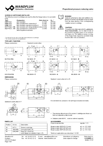
       TyPE lIST / FUNCTION                                                                                                        force increases on the a-side and on the b-side, respectively, whe-  conjunction  with  process  controls  allows  economical  solutions
       Flange construction:      Sandwich construction:
                                  A  P red.  T    B        A       P T      B        A      P T      B                             reby the pressure increases in port B and A, respectively. The valve   with repeatable processes.


                                  A  P red.  T    B         A      P T  20  B      10 A      P T  28  B  30                        operates practically independently of the input pressure. Pressure
                                                                    24                           14                                increase  in  the  consumer  port  to  above  the  adjusted  value,  e.g.
                                                                    22                                                               through an active consumer, is avoided by discharging excess oil to
        A       P T      B        A      P T      B       A red.   P T      B  ∗                A  P  B  G1/4"                     the tank. With the solenoid deenergised, the oil flows freely from
        A       P T      B                                                   22      A    27  14  P T T  B red.  20  40            consumer port to the tank. For the control, Wandfluh proportional
                                                                                                    To
                                  A       P T     B        A red.  P T      B        A       P T   B red.                          amplifiers are available (see register 1.13).

                                                             5,5
                                                           9,5
       MV.FA04-P/a               MV.SA04 - P              MV.SA04 - a              MV.SA04 - B
                                                           Ø  Ø  8  32                     82       38
                                  A  P red.  T     B       A       P T      B        A      P T      B                             SYMBOL
                                                                                             120
                                                                   40
                                  A  P red.  T     B        A      P T      B        A       P T     B
                                                                                                                                   simplified
                                                                    24                                                                          P / AB                               P / B                       P / A
                                                                    22
        A       P T      B                                A red.   P T      B                     P     G1/4"                                   A  B                                    A  B                   A  B
        A       P T      B        A       P T      B           ♦       ♦       ∗     A      P T  A  B B red.  40
                                                           A red.
                                  A
                                                                                     A
       MQ.FA04-P/a               MQ.SA04 - P P T   B      MQ.SA04 - a P T   B 22   MQ.SA04 - B P T T  B red.  26,8                         a           b                           a                                 b
                                                                                                    To
                                                                                                                                     a                        b             a                b               a               b
       DIMENSIONS                                           5,5    40                      82       38
                                                            Ø
       Flange construction                                  Sandwich construction in A or B  120                                                P  T                                    P  T                   P  T
                     20         10            28     30              18                                                            detailed
                 24                           14                                                                                                P / AB                               P / B                       P / A
                 22                                                                               P      G1/4"                                 A    B                               A    B                      A    B
                                                               ♦       ♦       ∗                A  B         40
                            ∗               A  P  B  G1/4"                   20                T    To     28,5                          a                 b                  a              b               a              b
                                       27  14            40
                          22               T     To    20   5,5
                                                            Ø      40                     83        39
       9,5  5,5                                                                             122                                                 To  P  T                             To  P  T                    To  P  T
       Ø  Ø   8  32                    82        38
                40                        120
                                                            For sandwich red. pressure in B cartridge is located on B-side.
       Sandwich construction in P
                 24
                 22                                                                                                                ACTUATION                                            INSTALLATION NOTES
                                                                                                                                    Actuation          Proportional solenoid, wet pin push   Mounting type  Flange mounting
                                              P
                            ∗               A   B    G1/4"
            ♦       ♦                                    40                                                                                            type, pressure tight                                 3 fixing holes for
                          22               T     To    26,8                                                                         Execution          W.S37 / 19 x 50 (Data sheet 1.1-173)                 socket head screws M5 x 40
                                                            ∗  The envelop dimensions of the screw-in cartridge are shown on
         5,5    40                                                                                                                                     M.S35 / 19 x 50 (Data sheet 1.1-174)  Mounting position  Any, preferably horizontal
         Ø                             82        38            their corresponding data sheets.
                                          120                                                                                       Connection         Connector socket EN 175301 – 803  Tightening torque  Fixing screws M  = 5,2 Nm (screw
                                                                                                                                                                                                                       D
                                                            ♦  Distance plate BDP4/... must be ordered separatly.                                      Connector socket AMP Junior-Timer                    quality 8.8, zinc coated)
                  18                                                                                                                                   Connector Deutsch DT04 – 2P                          M  = 5 Nm knurled nut
       PaRTS lIST                                           aCCESSORIES                                                                                                                                      D
                                                            Proportional amplifier            register  1.13                                                                            Note!    The length of the fixing screw depends on the base
        Position   Article   Description     A  P  B  G1/4"
                            ∗
           ♦        ♦                                    40  Distance plate BDP4/12 (12 mm)   art. no. 173.1450                                                                                  material of the connection element.
        10      617.3 ...   Screw-in cartridge  T  To  28,5  Distance plate BDP4/20 (20 mm)   art. no. 173.1451
                          20
        20  5,5  160.2052   O-ring ID 5,28x1,78             Distance plate BDP4/30 (30 mm)    art. no. 173.1452
                                       83
                40
        30  Ø   238.2406   Plug VSTI G1/4"-ED    39
                                         122
                         (only flange and sandwich type in P)  Technical explanation see data sheet 1.0-100
       Wandfluh AG        Tel.  +41 33 672 72 72   E-mail:  sales@wandfluh.com   Illustrations not obligatory   Data sheet no.
       Postfach           Fax  +41 33 672 72 12   Internet:  www.wandfluh.com   Data subject to change   2.3-820E 2/2                                 www.wandfluh.com  Illustrations are not binding  Data subject to change  1/4  Edition: 22 01  2.3-825 E
       CH-3714 Frutigen                                                                            Edition 14 04
       Page 1104
   1099   1100   1101   1102   1103   1104   1105   1106   1107   1108   1109