The intuitive parameterisation software

Parameterisation via block diagram with helpful analysis tools


PARAMETRISATION SOFTWARE PASO

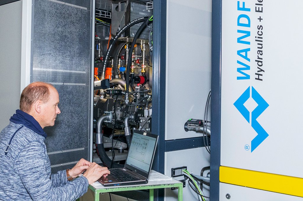
Whether a parameterisation software for proportional hydraulic valves can be handled intuitively and proves its worth becomes apparent at the latest when adapting a hydraulic system to mechanical equipment in the field. The software structure already provides a logically guided parameterisation process via a block diagram. In addition, all parameterisation steps can be monitored in real time via the various analysis tools.


What does parameterization mean?

In our case, parameterization means adjusting an electronic module to the desired range of functions via software and parameterization the individual functions so that the hydraulic system controls the mechanics of a system precisely and gently. This tuning takes place in an electronic module that controls oil flow through a proportional hydraulic valve. This variable oil flow finally drives a motor or a hydraulic cylinder that performs a specific function of a machine. As a rule, several motion sequences are controlled simultaneously in such a system. These must be precisely coordinated so that the mechanics do not become wedged and vibrations can be avoided. Correct parameterization of a system with a large number of valves can be very complex and take some time.


Parameterisation steps

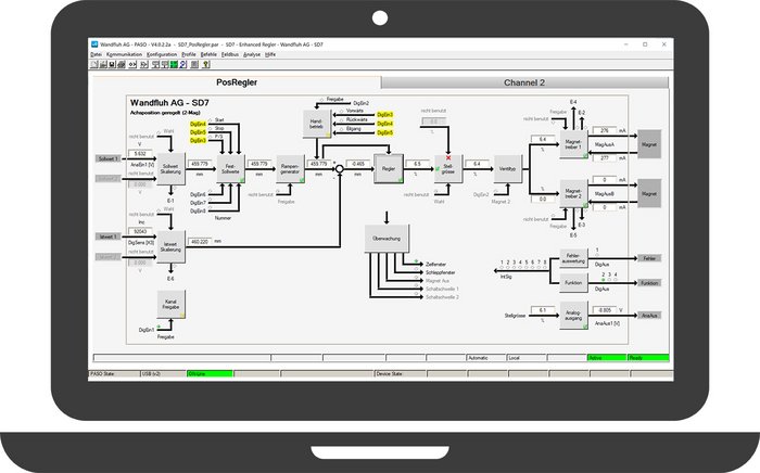
To make the individual parameterisation steps well-structured, the PASO software has been designed as a block diagram. When a parameterisation block is selected, an extra window opens in which the corresponding parameters can be set. The adjustment of a parameter affects the control system and thus the entire system in real time. In addition, in "manual mode", the individual valves can be opened and closed steplessly via the software, for example, to approach a specific point within the system. The following image shows the user interface of the PASO software with a description of the individual parameters in the table.


Block diagram fields
Field Function
Setpoint scaling The Wandfluh electronics can process various setpoint formats such as from a PLC, a joystick, a potentiometer, etc. The input signal is parameterised in the setpoint scaling setting block.
Actual value scaling In a control loop, the current position, the currently prevailing clamping pressure, the motor speed, etc. are recorded by corresponding sensors and the actual value is reported to the electronics as a so-called feedback signal. Since the different sensors can deliver different signal formats, scaling is also necessary here.
Fixed setpoints Instead of a variable setpoint, several fixed setpoints can also be stored in PASO. These can finally be activated and deactivated via a digital signal.
Ramp generator In order to avoid damage due to pressure surges or excessively fast movement sequences, steep edges in the setpoint signal can be specifically flattened by a ramp. In the amplifier electronics with a time ramp, in the controller electronics with acceleration, speed and deceleration.
Controller

The function block "Controller" is only displayed in connection with a feedback signal, i.e. in a controller mode.

  • Setpoint switching is used in conjunction with pressure control. It brings the manipulated variable of a pressure controller in advance to an approximate position in the correct range.
  • the P component amplifies the control difference: the higher the P component, the stronger the controller reacts (too high a P component leads to oscillation)
  • the I component is useful for pressure control and corrects the remaining control difference over time. The smaller the I time, the faster the controller reacts. Overshooting can be prevented with the additional I-windows
  • the D component is useful for fast controls. On the one hand, it has an accelerating effect when the setpoint value jumps, and on the other hand, it has a damping effect when the actual value approaches the setpoint value. The higher the D component and the smaller the D time, the stronger the controller reacts.
Positioning size In this function block, two signal channels can be combined, e.g. as a replacing control or pQ control: In the first channel Q-control in open loop, in the second channel p-control in closed loop.
Valve type Depending on the valve type and control (1-solenoid, 2-solenoid), the operating mode can be selected (e.g. setpoint bipolar +/-10V for a proportional spool valve). Wandfluh recommends the solenoid type "proportional solenoid with current control" so that temperature influences (change of coil resistance when heated) are automatically corrected. For special applications, this solenoid current control can be switched off, or the solenoid type "switching solenoid" can be selected.
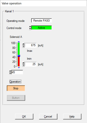
Magnetic driver The minimum current I-min should be set to the opening point of the valve. The maximum current I-max usually corresponds to the nominal current of the solenoid, unless you deliberately want to reduce the range of the valve. The dither is superimposed on the solenoid current and improves the valve's response and reduces the hysteresis. A good basic setting is 70 Hz / 200mA.
Manual operation For position control, it can make sense to define a speed for forward and for reverse and to call up this movement by means of a digital input. This is an alternative to the analogue setpoint signal.
Channel release The solenoid current is only output and the PID controller is only calculated if the electronics or the channel is enabled. This enable is also used to acknowledge any errors. This channel enable can be set by means of a digital input, or it can be set directly to On.


Tutorials

The following seven PASO tutorials on our Wandfluh YouTube channel provide an overview of how the parameterisation via block diagram and the analysis function work:


Commissioning process

During commissioning, the hydraulics must first be adapted to the mechanics of a system. In this process, all valves can be controlled individually via the PASO software and thus the system can be brought into certain working positions. This works much faster and easier via the manual mode than via the input of setpoints, especially since these are not known.


Real-time data analysis

A hydraulic system is an interaction of individual hydraulic valves controlled by one or more electronic modules or by an external PLC. The real-time data of the single valves are important indicators during commissioning and especially during troubleshooting. They provide indications as to why a system is not functioning as intended and give immediate feedback in the search for a solution, for example in the case of a defective solenoid, sensor or loose contact in an electrical line


Diagnostic monitor

In addition, the PASO software offers the possibility of displaying several signals on a time axis in a diagnostic monitor. For this purpose, the individual signals can be selected independently of each other and a trigger can be defined. The graphical visualisation of the time course makes the transient response and time shifts of signals visible and improvements through parameter adjustments can be made and analysed in real time. Finally, these signal curves can be recorded and stored as a trigger-controlled single curve or over a certain period of time.


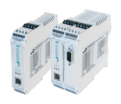
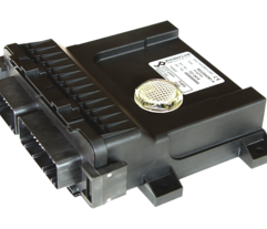
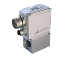
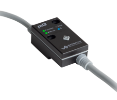
The electronic modules available on the market differ on the one hand in their technical features and characteristics and on the other hand in their construction. There are modules that only serve as amplifiers and electronic units that can be used for a complex pQ controlling system. In terms of construction, there are cards with snap locks for installation in control panels or small electronic amplifiers that fit directly onto a magnet, through to waterproof and shockproof electronic units for use in mobile applications.