
Page 951 - Softbound_Edition_19_en
P. 951
Proportional 1(P) Proportional
pressure relief valves
pressure relief valves 2(T) Proportional pressure relief valve
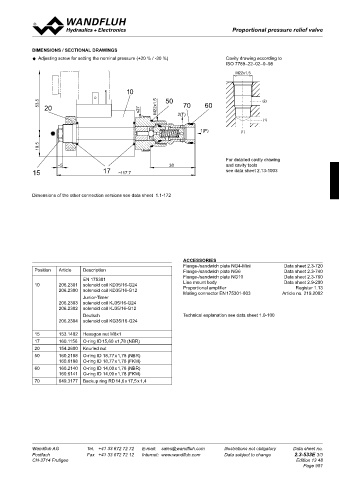
ElECTRICal SPECIfICaTIONS hyDRaUlIC SPECIfICaTIONS DIMENSIONS / SECTIONal DRawINGS
Construction Proportional solenoid, wet pin push type, Fluid Mineral oil, other fluid on request Adjusting screw for setting the nominal pressure (+20 % / -30 %) Cavity drawing according to
pressure tight Contamination efficiency ISO 4406:1999, class 18/16/13 ISO 7789–22–02–0–98
Standard-Nominal voltage U = 12 VDC U = 24 VDC (Required filtration grade ß 6…10 ≥ 75)
N
N
Limiting current I = 1250 mA I = 680 mA see data sheet 1.0-50/2 M22x1,5
2
G G Viscosity range 12 mm /s…320 mm /s
2
Relative duty factor 100 % DF (see data sheet 1.1-430) Fluid temperature -20…+70 °C
Peak pressure p = 400 bar
Protection class Connection version p max = 50 bar 10
acc. EN 60 529 D: IP 65 Tmax
J: IP 66 Nominal pressure ranges p = 63, 100 bar, 160 bar, 200 bar 53.5 50 70 60 (2)
N
G: IP 67 / IP69 K acc. EN 40050 Volume flow Q = 5…100 l/min 20 M22x1.5
with p = 63 / 100 / 160 bar s27
N
For further electrical specifications see data sheet 1.1-172 Q = 10…100 l/min 2(T)
with p = 200 bar (1)
N
Leakage volume flow see characteristics
Hysteresis ≤ 5% ∗ 1(P) (1)
∗ at optimal dither signal
19.5
For detailed cavity drawing
ChaRaCTERISTICS Oil viscosity υ = 30 mm /s ~5 38 and cavity tools
2
p = f (Q) Pressure volume flow characteristics p= f (Q) Pressure volume flow characteristics 15 17 see data sheet 2.13-1003
(Maximum adjustable pressure) (Minimum adjustable pressure) ~117.7
p [bar] p [bar]
300 K4040 40 K4041
250 P N = 200 bar 30 Dimensions of the other connection versions see data sheet 1.1-172
200 P N = 160 bar
150 P N = 100 bar 20 P N = 160/200 bar
100 P N = 63bar P N = 63/100 bar
50 10
0 0
0 25 50 75 100 Q [l/min] 0 25 50 75 100 Q [l/min]
p = f (l) Pressure adjustment characteristics Q = f (p) Leakage volume flow characteristics
L
(Q = 5 l/min)
p [bar] Q [cm /min] aCCESSORIES
3
125 K4042 200 K4043 Flange-/sandwich plate NG4-Mini Data sheet 2.3-720
100 150 Position Article Description Flange-/sandwich plate NG6 Data sheet 2.3-740
75 EN 175301 Flange-/sandwich plate NG10 Data sheet 2.3-760
Data sheet 2.9-200
Line mount body
100 10 206.2301 solenoid coil KD35/16-G24
50 206.2300 solenoid coil KD35/16-G12 Proportional amplifier Register 1.13
25 50 Junior-Timer Mating connector EN 175301-803 Article no. 219.2002
0 0 206.2303 solenoid coil KJ35/16-G24
0 10 20 30 40 50 60 70 80 90 100 l [%] 0 50 100 150 200 p [bar] 206.2302 solenoid coil KJ35/16-G12
Deutsch Technical explanation see data sheet 1.0-100
Adjustable range of nomial pressure, adjusted solenoid coil KG35/16-G24
with set screw.. 206.2304
15 153.1402 Hexagon nut M8x1
17 160.1156 O-ring ID 15,60 x1,78 (NBR)
20 154.2600 Knurled nut
50 160.2188 O-ring ID 18,77 x 1,78 (NBR)
160.6188 O-ring ID 18,77 x 1,78 (FKM)
60 160.2140 O-ring ID 14,00 x 1,78 (NBR)
160.6141 O-ring ID 14,00 x 1,78 (FKM)
70 049.3177 Backup ring RD 14,6 x 17,5 x 1,4
Wandfluh AG Tel. +41 33 672 72 72 E-mail: sales@wandfluh.com Illustrations not obligatory Data sheet no. Wandfluh AG Tel. +41 33 672 72 72 E-mail: sales@wandfluh.com Illustrations not obligatory Data sheet no.
Postfach Fax +41 33 672 72 12 Internet: www.wandfluh.com Data subject to change 2.3-533E 2/3 Postfach Fax +41 33 672 72 12 Internet: www.wandfluh.com Data subject to change 2.3-533E 3/3
CH-3714 Frutigen Edition 13 48 CH-3714 Frutigen Edition 13 48
Page 951