Page 944 - Softbound_Edition_19_en
P. 944

Proportional pressure relief valve
                                                                             Proportional pressure relief valve                                                                                           Proportional pressure relief valve


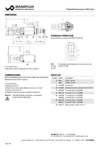
       DIMENSIONS                                                                                                                  Proportional pressure relief cartridge
                                                                                                                                    ◆  pilot operated                                   M22 x 1,5
                                                                         X                                                          ◆  Q  = 100 l/min                                   ISO 7789
                                                                                                                                       max
                                                                                                                                    ◆  p  = 400 bar
                                            s30                                                                                       p max   = 350 bar
                  15                        M22x1.5                                                                                    ◆  N max
         76.8   MD=10Nm                          (2)
          37.1   E  s6                               (1)                                                                           DESCRIPTION                                          APPLICATION
           W =  X  *                                                                                                               Pilot  operated  proportional  pressure  relief  valve  in  screw-in     The electrical remote control in conjunction with process controls
                                                                                                                                   cartridge construction for cavity according to ISO 7789. High flow
                                                                                                                                                                                        allows  economical  solutions  with  repeatable  processes.  The
                      12  17   10     18      50  70  60   HYDRAULIC CONNECTION                                                    capacity, very sensitively adjustable. When the operating pressure   screw-in cartridge is perfectly suitable for installation in control
                   MD=5Nm                                  Cavity drawing according to ISO 7789–22–02–0–98                         adjusted  by  means  of  the  proportional  solenoid  is  reached,  the     blocks and is installed in sandwich-  (vertical stacked systems) and

                    34.7         78.4          38.5                                                                                valve opens and connects the protected line with the drain to the   in  flange  plates  (corresponding  data  sheets  in  this  register).  For
                                                                                 M22x1.5
                                 151.6                                                                                             tank. The back pressure in T (2) affects the pressure in P (1). For the   machining the cartridge cavity in steel and aluminum blocks, cavity
                                                                                                                                   control,  Wandfluh  proportional  amplifiers  are  available  (see     tools  are  available  (hire  or  purchase).  Please  refer  to  the  data
                                                                                                                                   register 1.13).                                      sheets in register 2.13.


                                                                                          (2)
           74.8                                                                           (1)
             35                                                                                                                    SYMBOL                                               ACTUATION
              M =                                                                 (1)                                                                                                    Actuation          Proportional solenoid, wet pin push
                                                                                                                                          (T) 2                                                             type, pressure tight
                               10                          Note!    For detailed cavity drawing and cavity tools see data                                                                Execution          W.S37 / 19 x 50 (Data sheet 1.1-173)
       E = Air bleed screw                                          sheet 2.13-1003                                                                                                                         M.S35 / 19 x 50 (Data sheet 1.1-174)
       *Adjustment screw for adjusting the nominal pressure                                                                                                                              Connection         Connector socket EN 175301 – 803
                                                                                                                                          (P) 1                                                             Connector socket AMP Junior-Timer
                                                                                                                                                                                                            Connector Deutsch DT04 – 2P
       COMMISSIONING                                       PARTS LIST
       When commissioning, the valve must be vented under pressure as   Position Article  Description                              TYPE CODE
       follows (see detail X in Dimensions):                                                                                                                                                  B  V  P  PM22  -     -     /        -        #
                                                                 10 206.2…  W.S37 / 19 x 50                                         Pressure relief valve
                                                                    260.5…  M.S35 / 19 x 50
       ◆  Loosen lock nut                                                                                                           Pilot operated
       ◆  Remove screw (E)                                       12 154.2700  Knurled nut
       ◆  Push the non-return valve (with pin or hex key < 1,3 mm)  15 153.2401  Dichtmutter Norm „Seal-Lock” 8 Zi - Ni M8          Proportional
       ◆  Screw-in the screw (E)                                 17 160.2187  O-ring ID 18,72 x 2,62 (NBR)
       ◆  Adjust the required pressure and tighten the lock nut                                                                     Screw-in cartridge M22 x 1,5
                                                                 18 160.2170  O-ring ID 17,17 x 1,78 (NBR)
       Attention!   Therewith oil flows out with the corresponding   50 160.2188  O-ring ID 18,77 x 1,78 (NBR)                      Nominal pressure range p    20 bar   20   200 bar       200
                                                                                                                                                     N
               pressure! Cover with a cloth.                        160.6188  O-ring ID 18,77 x 1,78 (FKM)                                                 63 bar       63    275 bar       275
                                                                 60 160.2140  O-ring ID 14,00 x 1,78 (NBR)                                                 100 bar      100   350 bar       350
                                                                                                                                                           160 bar
                                                                                                                                                                        160
                                                                    160.6141  O-ring ID 14,00 x 1,78 (FKM)
                                                                 70 049.3177  Back-up ring rd 14,6 x 17,5 x 1,4                     Nominal voltage U      12 VDC       G12
                                                                                                                                                N
                                                                                                                                                           24 VDC       G24
                                                                                                                                                           without coil   X5
                                                                                                                                    Slip-on coil           Metal housing round              W
                                                                                                                                                           Metal housing square             M
                                                                                                                                    Connection execution   Connector socket EN 175301-803 / ISO 4400   D
                                                                                                                                                           Connector socket AMP Junior - Timer   J
                                                                                                                                                           Connector Deutsch DT04 - 2P      G
                                                                                                                                    Sealing material       NBR
                                                                                                                                                           FKM (Viton)   D1

                                                                                                                                    Manual override        Manual override                 HB4,5
                                                                                                                                                           Screw plug                      HB0

                                                           Wandfluh AG  Postfach  CH-3714 Frutigen                                  Design index (subject to change)
                                                           Tel. +41 33 672 72 72  Fax +41 33 672 72 12  sales@wandfluh.com          2.3-529

                         www.wandfluh.com  Illustrations are not binding  Data subject to change  4/4  Edition: 19 28  2.3-528 E                      www.wandfluh.com  Illustrations are not binding  Data subject to change  1/3  Edition: 17 41  2.3-529 E
       Page 944
   939   940   941   942   943   944   945   946   947   948   949