Page 939 - Softbound_Edition_19_en
P. 939

Proportional pressure relief valve
                                                                                   Proportional pressure relief valve


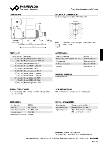
            DIMENSIONS                                           HYDRAULIC CONNECTION
                                                                 Cavity drawing according to ISO 7789–18–02–0–98

                    30                                                                 M18x1.5
                                              s24
                    15
               68.8   MD=5.5Nm                 M18x1.5                                          (2)


                  29                                                                            (1)


                                                                                       (1)
                    40          10     18       50     70  60
               MD= 1.2Nm                                         Note!    For detailed cavity drawing and cavity tools see data
                         10.3      52.7          28.8                     sheet 2.13-1001
                                      91.8


            PARTS LIST                                           ACCESSORIES
              Position Article  Description                       Proportional amplifier          Register 1.13
                  10 256.2418  Proportional solenoid PI29V-G12    Flange body / sandwich plate NG3-Mini  Data sheet 2.3-700
                     256.2453  Proportional solenoid PI29V-G24    Threaded body                   Data sheet 2.9-200
                  15 253.8000  Manual override HB4,5              Technical explanations          Data sheet 1.0-100
                  18 160.2120  O-ring ID 12,42 x 1,78 (NBR)       Filtration                      Data sheet 1.0-50
                  30 219.2002  Electric plug B (black)
                  40 249.0006  Socket head screw M3 x 42
                  50 160.2156  O-ring ID 15,60 x 1,78 (NBR)      MANUAL OVERRIDE
                     160.6156  O-ring ID 15,60 x 1,78 (FKM)
                                                                 HB4,5 as standard
                  60 160.2093  O-ring ID 9,25 x 1,78 (NBR)
                     160.6092  O-ring ID 9,25 x 1,78 (FKM)
                  70 049.3137  Backup ring rd 10,6 x 13,5 x  1,4


            SURFACE TREATMENT                                    SEALING MATERIAL
             ◆  All external parts of the cartridge as well the solenoid coil are   NBR or FKM (Viton) as standard, choice in the type code
               zinc-nickel coated


            STANDARDS                                            INSTALLATION NOTES
             Cartridge cavity    ISO 7789                         Mounting type      Screw-in cartridge M18 x 1,5
             Solenoids           DIN VDE 0580                     Mounting position  Any, preferably horizontal
             Connection execution D  EN 175301 – 803              Tightening torque  M  = 40 Nm Screw-in cartridge
                                                                                      D
             Protection class    EN 60 529                                           M  = 1,2 Nm solenoid screws
                                                                                      D
             Contamination efficiency  ISO 4406


                                                                 Wandfluh AG  Postfach  CH-3714 Frutigen
                                                                 Tel. +41 33 672 72 72  Fax +41 33 672 72 12  sales@wandfluh.com

                               www.wandfluh.com  Illustrations are not binding  Data subject to change  3/3  Edition: 19 15  2.3-520 E
                                                                                                            Page 939
   934   935   936   937   938   939   940   941   942   943   944