
Page 909 - Softbound_Edition_19_en
P. 909
Pressure reducing valve
Pressure reducing valve
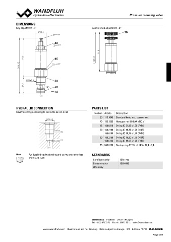
DIMENSIONS
Key adjustment „S” Control knob adjustment „D”
26.5 20
s4
40
s17
91.8
91.5 45 129.5
129.2 s27
M22x1.5 50
37.7 2(P) 60
70
1(A)
HYDRAULIC CONNECTION PARTS LIST
Cavity drawing according to ISO 7789–22–01–0–98 Position Article Description
20 113.1049 Standard knob incl. counter nut
M22x1.5
40 153.1505 Hexagon nut 0,8d A4 M10 x 1
45 160.6218 O-ring ID 21,95 x 1,75 (FKM)
50 160.2188 O-ring ID 18,77 x 1,78 (NBR)
(2)
160.6188 O-ring ID 18,77 x 1,78 (FKM)
60 160.2156 O-ring ID 15,60 x 1,78 (NBR)
(1) 160.6156 O-ring ID 15,60 x 1,78 (FKM)
70 049.8196 Backup ring PTSM rd 14,5 x 17,4 x 1,4
(1)
Note! For detailed cavity drawing and cavity tools see data STANDARDS
sheet 2.13-1008
Cartridge cavity ISO 7789
Contamination ISO 4406
efficiency
Wandfluh AG Postfach CH-3714 Frutigen
Tel. +41 33 672 72 72 Fax +41 33 672 72 12 sales@wandfluh.com
www.wandfluh.com Illustrations are not binding Data subject to change 3/3 Edition: 19 18 2.2-532 E
Page 909