
Page 887 - Softbound_Edition_19_en
P. 887
Accumulator unloading valves Accumulator unloading valve
Accumulator loading valves
sYmBol Accumulator loading valve
Flange construction NG6
• 2-point-adjustment ISO 4401-03
• Q max = 30 l/min
• p max = 400 bar
• p = 350 bar
N max
DESCRIPTION FUNCTION APPLICATION
Flange typ pilot operated accumulator loading The accumulator loading valve diverts pump Accumulator loading valves are used in hydrau-
valve. Mounting interface acc. to ISO 4401-03. flow back to tank at low ∆p afther upper wor- lic systems with accumulator. Systems with low
remarK! screw-in cartridges installed 3 pressure ranges are available. The upper king pressure of the accumulator has been energy comsumption and reduced installation
Detailed performance data and additional hydraulic speci- The following screw-in cartridges are used in the sandwich body: and lower shifting pressure are adjustable reached and to load the accumulator when costs may be built where oil demand of a cy-
fications may by drawn from the data sheets of the corres- in dependently from each other. A minimum pressure of the stared fluid drops to the lower linder varies or for load holding functions eg.
ponding installed pressure relief cartridge. Type Designation Data sheet no. pres-sure difference must be observed. Spools working pressure. Hydraulic circuits with short clamping functions.
US.PM22 Accumulator unloading valve are of hardened steel, body is of high grade time peak consumption of fluids may be built Important:
20 • pilot operated 2.1-548 hy-draulic cast iron for long service life. by combining a pump with relativly low deli- - An additional relief valve for system protection
caution! 10 very and an accumulator. Energy input will has to be installed. The relief valve setting must
The performance data especially the „pressure-flow- be reduced. be above the upper shifting pressure of the
characteristic„ on the data sheets of the screw-in catridges Important: accumulator loading valve.
refere to the screw-in cartridges only. The additional press- For loading an accumulator a check valve for - Drain port A needs a separate tank line
ure drop of the flange body respectivly sandwich body must free flow from P to B line is necessairy (Sand- as back pressure influences the pressure
be taken into consideration. ∗ wich plate NG6: ARV6/P-B must be ordered settings.
separatly). - Gas charge of the accumulator may not ex-
ceed 90 % of lower shifting pressure.
dimensions TYPE CODE
A SPLV 6 2 / #
20 10
International mounting interface ISO
Accumulator loading valve
Nominal size 6
∗ 2 adjustable shifting pressures
20 10 Pressure range p 63 bar p1
N
160 bar
p2
350 bar p3
Design-Index (Subject to change)
∗
GENERAL SPECIFICATIONS HYDRAULIC SPECIFICATIONS
∗ The exterior dimensions of the cartridge can be obtained from the Description Pilot operated accumulator loading valve Fluid Mineral oil, other fluid on request
corresponding data sheet 2.1-548 Norminal size NG6 acc. to ISO 4401-03 Contamination efficiency ISO 4406:1999,
Construction Flange construction class 18/16/13...21/19/15
Mounting Flange (Required filtration grade ß6...25≥75)
4 fixing holes for head cap screws M5x45 refer to data sheet 1.0-50/2
PARTS LIST set-uP and connection exemPles (with in addition ARV6/P-B: socket head Viskosity range 12 mm /s…320 mm /s
2
2
Unloading point adjusted at 100 bar (OS) cap screws M5x88) Fluid temperature -20…+70°C
Position Article Description Differential value 15 % Connections Connection plates Peak pressure p max = 400 bar
Loading point: (US) = OS minus 15 % = 85 bar Multi-station flange subplate Norminal pressure p p1 = 63 bar, p2 = 160 bar, p3 = 350 bar
N
10 160.2093 O-ring ID 9,25x1,78 Gas side of accumulator loaded upto max. 90 % of US = 76 bar Longitudinal stacking system Minimum pressure p p1: 20 bar, p2/p3: 25 bar
min
20 238.2406 Plug VSTI G1/4"-ED Ambient temperature -20…+50°C Min. shifting pressure diff. p1: 15 bar, p2: 25 bar, p3: 30 bar
Mounting position any Pressure adjustment p1: 12 bar/turn, p2: 20 bar/turn
Fastening torque M = 5,5 Nm (quality 8.8) p3: 40 bar/turn
D
Weight m = 2,7 kg Volume flow Q = 1…30 l/min
Leakage volume flow see characteristics
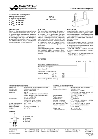
SYMBOL
B
P: Pressure port
P T T: Tank port
A: Drain port
Technical explanation see data sheet 1.0-100 B: Pilot port
A
Wandfluh AG Tel. +41 33 672 72 72 E-mail: sales@wandfluh.com Illustrations not obligatory Data sheet no. Wandfluh AG Tel. +41 33 672 72 72 E-mail: sales@wandfluh.com Illustrations not obligatory Data sheet no.
Postfach Fax +41 33 672 72 12 Internet: www.wandfluh.com Data subject to change 2.1-940E 2/2 Postfach Fax +41 33 672 72 12 Internet: www.wandfluh.com Data subject to change 2.1-950E 1/2
CH-3714 Frutigen Edition 03 35 CH-3714 Frutigen Edition 08 30
ARV6/P-B Page 887
42
P B T A
M