
Page 791 - Softbound_Edition_19_en
P. 791
2
3
1
D
A
13
7
X5
12
18
B
46.2 4 A (2 : 1) 1 6 5 X1 6 G X8 X7 F E X6 (1 : 1) 7 C X4 X3 B X2 A 8 A B
60
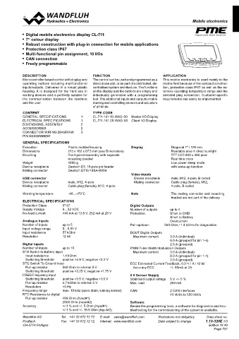
83 44.5 27 A Mobile electronics display CL-711
Mobile electronics
C 23 C
10
• Digital mobile electronics display CL-711 Programmable Mobile Electronics
213
• 7“ colour display 204.2
102.2
• Robust construction with plug-in connection for mobile applications
38.1
• Protection class IP67
• Multi-functional pin assignment, 10 I/Os
D D
• CAN connection
• Freely programmable
162 154.5 30 1
69.4
DESCRIPTION 18 4x 10-24 UNC FUNCTION APPLICATION
Microcontroller based control with display and The control can be used and programmed as a This mobile electronics is used mainly in the
E 01 02 09.06.2016 BEH Anschluss im Detail dargestellt; 3D-Ansicht gedreht Gezeichnet 31.03.2016 BEH E
BR
16.12.2016
BEH
Beschriftung dazu
Geprüft
28.11.2016
operating buttons including multifunctional stand alone unit, or as part of a distributed, de- mobile field because of the compact construc- Serie freigegeben BR
16.12.2016
BEH
Freigegeben
Gewinde vermasst
16.12.2016
03
M 1:2
Änderungsbeschrieb
Datum
Rev.
Name Änderungsnr.
inputs/outputs. Delivered in a robust plastic centralised system architecture. The functions tion, protection class IP67 as well as the ex- 0.613 kg
Gewicht
Ersetzt durch:
Mobilelektronik Display
Ersatz für:
Dok.-Nr.
0195544
CL-711
housing, it is designed for the hard use in on the display and the buttons are simply and tensive operating temperature range and the Format
A2
Dokument darf ohne schriftliche Einwilligung weder kopiert,
Revision
Art.-Nr.
DB 1.13-320
working devices and is perfectly suitable for individually generated with a programming selected plug connection. Customer-specific Blatt 1 von 1
03
verwertet noch an Dritte weitergegeben werden.
Zuwiderhandlung ist strafbar und wird gerichtlich verfolgt.
1
5
2
4
C:\00_Wandfluh\Verkauf\Dokumentation\Reg1.13\0195544
3
the communication between the machine tool. The additional inputs and outputs enable requirements can easily be implemented.
and the user. reading and controlling sensors and actuators
of all kinds.
CONTENT TYPE CODE
GENERAL SPECIFICATIONS 1 CL-711-101-10-WAG-00 Master I/O Display
ELECTRICAL SPECIFICATIONS 1 CL-711-101-20-WAG-00 Client I/O Display
DIMENSIONS, ASSEMBLY 2
ACCESSORIES 2
CONNECTOR WIRING DIAGRAM/ 3
PIN ASSIGNMENT
GENERAL SPECIFICATIONS
Execution Plastic molded housing Display Diagonal 7" / 178 mm
Dimensions 213 x 162 x 67.5 mm (see Dimensions) Readable also in direct sunlight
Mounting Front panel assembly with separate TFT LCD 800 x 480 pixel
mounting bracket Real time clock
Weight 1000 g Low power sleep mode
Device receptacle Deutsch DT, 18-pole pin header with wake-up function
Mating connector Deutsch DT16-18SA-K004
Video inputs
USB connector Device receptacle male, M12, 4-pole, B coded
Device receptacle male, M12, 4-pole Mating connector Cable plug (female), M12,
Mating connector Cable plug (female), M12, 4-pole 4-pole, B coded
Working temperature -40....+70°C Note The mating connector and mounting
bracket are not part of the delivery
ELECTRICAL SPECIFICATIONS
Protection Class IP 67 Digital Outputs
Supply Voltage 8…32 VDC Number of outputs up to 4
No-load current 440 mA at 13.8 V, 252 mA at 28 V Protection Short to GND
Short to Battery
Analogue inputs Overcurrent
Number of inputs up to 5 Pull-up/down 560 Ohm / 1.4 kOhm for diagnostics
Input voltage range 0…5.51 V
Input resistance 57 kOhm DOUT Digital Outputs
Resolution 12 bit Maximum current 3.0 A (individual)
8.0 A (grouped for pin 1-4)
Digital inputs 2.5 A (grouped)
Number of inputs up to 10 PWM Pulse Width Modulation Outputs
STB Switch to Battery input Maximum current 3.0 A (individual)
Input resistance 1.4 kOhm 8.0 A (grouped for pin 1-4)
Switching threshold positive >5.9 V, negative <3.2 V 2.0 A (grouped)
STG Switch To Ground input ECC Estimated Current Feedback, 0.2-4.1 A / 12 bit
Pull-up resistor 560 Ohm to internal 5 V Accuracy ECC +/- 50mA at 2A
Switching threshold positive >3.25 V, negative <1.75 V
FREQ Frequency input 5 V Sensor Supply
Switching threshold positive >3.5 V, negative <1.0 V Stabilised output voltage 5 V +/- 5 %
Pull-up resistor 4.7 kOhm to internal 5 V Max. load 250 mA
Resolution <5 Hz
Frequency range max. 10 kHz (open drain, sinking sensor) CAN 2 CAN interfaces
RTD Resistance to digital 40 kbit/s to 500 kbit/s
Pull-up resistor 499 Ohm (Input#1)
2000 Ohm (Input#2) Software
Accuracy +/-1 % and +/- 5 Ohm (Input#1) Beside the programming tools, a software for diagnostics and trou-
+/-1 % and +/- 19.5 Ohm (Input#2) bleshooting for the commissioning of the system is available.
Wandfluh AG Tel. +41 33 672 72 72 E-mail: sales@wandfluh.com Illustrations not obligatory Data sheet no.
Postfach Fax +41 33 672 72 12 Internet: www.wandfluh.com Data subject to change 1.13-320E 1/3
CH-3714 Frutigen Edition 16 49
Page 791