
Page 76 - Softbound_Edition_19_en
P. 76
Solenoid
Solenoids Solenoids
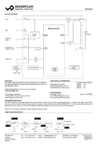
BLOCK DIAGRAM AMPLIFIER WITH ANALOGUE INTERFACE
Command value scaling Signal recording
X1-1 X2-1 The command value can be applied as a voltage, current, digital, fre- Furthermore, the „PD2“ amplifier electronics have a signal recording
+VCC
quency or PWM signal. The scaling takes place via the parameter “In- Supply F F
function. This, by means of PASO, enables the recording of various sy-
stem signals, such as command value, solenoid current, etc., which
terface”. Furthermore, the command value can be monitored for a cable voltage X1-1 Tension X1-2
X1-5
X1-5
d'alimentation
break. A dead band can also be set. can be represented on a common time axis.
F = Fuse low F = Sécurité inerte
Fixed command value Solenoid driver F F
A Pulse-Width-Modulated current output is available. A dither signal is
X1-5 There is 1 fixed command value available, which can be selected via Supply X1-1 Tension X1-2
voltage
X1-5
X1-5
GND the digital input. This function has to be configurated before in PASO. superimposed, whereby the dither frequency and the dither level are d'alimentation
separately adjustable. The minimum (Imin) and maximum (Imax) cur- F = Sécurité inerte
F = Fuse low
Internal Solenoid Ramp generator rent can be adjusted. The solenoid output can also be configurated as
supply Supply PWM Two linear ramps for up and down are available which can be adjusted switching solenoid output. In this case, a power reduction can be ad-
USB/PASO
separately. justed.
Stabilised X1-4
output Valve type Optimisation of characteristic curve F
0...1 VDC
F
Adjustment possibilities: switching solenoid or proportional solenoid. Supply X1-1 X1-3 Tension X1-2
An adjustable characteristic curve „Command value input – solenoid
6...32 VDC
X1-5
A/D voltage USB/PASO d'alimentation X1-5
current output“ enables an optimised (e.g. linearised) characteristic of
Mode of operation „Command value unipolar/bipolar (1-Sol) the hydraulic system. F = Sécurité inerte
F = Fuse low
X1-2 Dependent on a command value signal (voltage, current, digital, fre-
Analogue input X2-2 USB/PASO Adapter
0...1 VDC
Voltage or current A/D quency or PWM), the solenoid is driven (e.g. 0….10V correspond to Channel enabling USB-PD2 X1-3
6...32 VDC
0….100 % command value, 0….+100 % command value correspond The device is enabled as per factory setting. Via PASO or menu item,
to Imin….Imax solenoid driver) the digital input can the enabling can be set „on“, „out“ or „external“
0...1 VDC
(digital input). X1-3
6...32 VDC Adapter
USB/PASO USB-PD2
Hints: USB/PASO
X1-3 Digital input: if not wired, the state of the digital input is not defined
Digital input 0...1 VDC
Analogue input: if not wired, the voltage input will read 1.11 V
X1-3
0...1 VDC
6...32 VDC constantly. X1-3
6...32 VDC
Adapter Push-buttons 7 segment X1-4 Adapter
USB-PD2 FLASH display 0 % 100 % Command value USB/PASO USB-PD2
RAM 0 V 10 V X1-2
4 mA 20 mA Analogue value
PASO / USB 0 mA 20 mA 0...1 VDC X1-5
5 Hz 5000 Hz 6...32 VDC X1-4 X1-3
- 10 V 10 V
X1-2
START-UP ADDITIONAL INFORMATION CONNECTION EXAMPLES X1-5
Information regarding installation and commissioning are contained in Wandfluh documentation
the information leaflet supplied with the amplifier electronics and in the Proportional spool valve register 1.10 F F
Supply voltage
operating instructions. Proportional pressure valves register 2.3 Supply X1-1 Analogue input with potentiometer Tension X1-2
X1-5
X1-5
voltage
Proportional flow control valves register 2.6 F X1-4 d'alimentation F
Additional information can be found on our website: Supply F = Fuse low X1-1 Tension F = Sécurité inerte X1-2
voltage
X1-5
X1-5
«www.wandfluh.com» X1-2 d'alimentation
ACCESSORIES F = Fuse low F = Sécurité inerte
Free-of-charge download: USB adapter PD2 Article no. 726.9900 0...10 VDC X1-5 X1-2
+/-10 VDC
X1-5
• «PASO-PD2» Parameterisation software incl. USB cable type A-B, 1,8 m
• Operating instruction (*.pdf) (for parameterisation via PASO) Digital input as function input Analogue input voltage with external voltage source
USB/PASO
PARAMETER SETTINGS 0...10 VDC X1-2
The MKY electronics have push-buttons and a display which enable setting the most important parameters. In addition, the digital input can be +/-10 VDC X1-5
used as a communication interface, through which, by means of the parameterisation software "PASO-PD2", the complete parameterisation and 0...1 VDC USB/PASO Analogue input current with external current source
diagnostics can be carried out. For this, the Wandfluh USB-PD2 adapter is required. (not included in the delivery) 6...32 VDC X1-3
0...1 VDC 0...20 mA X1-2
Attention: During the communication, the digital input cannot be used. 6...32 VDC X1-3 4...20 mA X1-5
Adapter
FUNCTION DESCRIPTION Digital input as USB interface
USB/PASO
USB-PD2
X1-2
0...10 VDC
Adapter VCC 0...20 mA X1-2
X1-5
+/-10 VDC
USB/PASO USB-PD2 4...20 mA X1-5
0...1 VDC
6...32 VDC X1-3 X1-1 + VCC
0...1 VDC
PC USB USB - Adapter ON DIG X1-3 DigInp MKY
TX
6...32 VDC
Command Solenoid output PASO X1-3 RX OV X1-5
value Command Fixed Ramp Solenoid GND
scaling command generator Valve type
values driver Current measurement
GND
0...20 mA X1-2
DigInp DigInp DigInp DigInp Plug Screw Terminal 4...20 mA X1-5
USB type B
Error Number Enable Solenoid Enable Error X1-4
X1-2 X1-4
Wandfluh AG Tel. +41 33 672 72 72 E-mail: sales@wandfluh.com Illustrations not obligatory Data sheet no. Wandfluh AG Tel. +41 33 672 72 72 E-mail: sales@wandfluh.com Illustrations not obligatory Data sheet no.
Postfach Fax +41 33 672 72 12 Internet: www.wandfluh.com Data subject to change 1.1-183E 4/5 Postfach X1-5 X1-2 Fax +41 33 672 72 12 Internet: www.wandfluh.com Data subject to change 1.1-183E 5/5
CH-3714 Frutigen Edition 22 11 CH-3714 Frutigen Edition 22 11
Page 76 X1-5
0...10 VDC X1-2
+/-10 VDC X1-5
0...10 VDC X1-2
+/-10 VDC X1-5
0...20 mA X1-2
4...20 mA X1-5
0...20 mA X1-2
4...20 mA X1-5