
Page 264 - Softbound_Edition_19_en
P. 264
Spool valve
Spool valve Spool valve
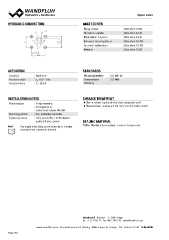
HYDRAULIC CONNECTION ACCESSORIES Spool valve
Fixing screws Data sheet 1.0-60 Flange construction NG6
17.8 ISO 4401-03
Threaded subplates Data sheet 2.9-30 ◆ roller operated
T 4/2-way with spring reset
Multi-station subplates Data sheet 2.9-60 ◆
◆ Q = 80 l/min
A B Horizontal mounting blocks Data sheet 2.9-100 max
31 21 32.5 ◆ p = 350 bar
Technical explanations Data sheet 1.0-100 max
P
Filtration Data sheet 1.0-50
21.5
40.5 DESCRIPTION APPLICATION
Direct operated valve, roller operated with 4 connections in 5 Spool valves are mainly used for controlling direction of movement
chamber design. Without actuation, the spool is switched back to and stopping of hydraulic cylinders and motors. The direction of
the offset position. movement is determined by the position of the spool and its symbol.
Manually or mechanically operated valves are particularly suitable
ACTUATION STANDARDS for use in installations where no electric current is available or for
Actuation Hand lever Mounting interface ISO 4401-03 applications in explosion hazard areas.
Actuation angle a = 8,9° / side Contamination ISO 4406
b
Actuation force F = 21,5 N efficiency
b
TYPE CODE
WD T F A06 - - #
INSTALLATION NOTES SURFACE TREATMENT Spool valve, direct operated
Mounting type Flange mounting ◆ The valve body is painted with a two component paint Roller with spring reset
4 fixing holes for ◆ The hand lever housing and the cover are zinc-nickel coated
socket head screws M5 x 50 Flange construction
Mounting position Any, preferably horizontal
International standard interface ISO, NG6
Tightening torque Fixing screws M = 5,2 Nm (screw
D
quality 8.8, zinc coated) SEALING MATERIAL Designation of symbols acc. to table Operation a-side …1
NBR or FKM (Viton) as standard, choice in the type code Operation b-side …2
Note! The length of the fixing screw depends on the base
material of the connection element. Sealing material NBR
FKM (Viton) D1
Design index (subject to change)
1.5-46
GENERAL SPECIFICATIONS HYDRAULIC SPECIFICATIONS
Designation 4/2-spool valve Working pressure p = 350 bar
max
Construction Direct operated Tank pressure p T max = 100 bar
Mounting Flange construction Maximum volume flow Q = 80 l/min, see characteristics
max
Nominal size NG6 according to ISO 4401-03
Actuation Roller operated Leakage oil See characteristics
Ambient temperature -25…+70 °C (NBR) Fluid Mineral oil, other fluid on request
-20…+70 °C (FKM) Viscosity range 12 mm /s…320 mm /s
2
2
Weight 1,27 kg Temperature range -25…+70 °C
fluid
Contamination Class 20 / 18 / 14
ACTUATION efficiency
Actuation Roller Filtration Required filtration grade ß 10…16 ≥ 75,
Actuation stroke s = 2,6 mm see data sheet 1.0-50
Actuation force F = 110 - 135 N at p
b T max
Wandfluh AG Postfach CH-3714 Frutigen
Tel. +41 33 672 72 72 Fax +41 33 672 72 12 sales@wandfluh.com
www.wandfluh.com Illustrations are not binding Data subject to change 4/4 Edition: 21 43 1.5-41 E www.wandfluh.com Illustrations are not binding Data subject to change 1/3 Edition: 18 18 1.5-46 E
Page 264