Page 1179 - Softbound_Edition_19_en
P. 1179

A
                                                          B
                                                  PT
                                                                                   PT
                                                                           A
                 PT
          A
                                           A
                          B
                                                                                           B
                                           A
                                                                                           B
                          B
                 PT
          A      PT       B                A      PT      B                A       PT      B
                                                  PT
                                                                           A
                                                          B
                                                                                   PT
 Flow control valves                                                                            Flow control valves
                                                                                                 Flow control valve
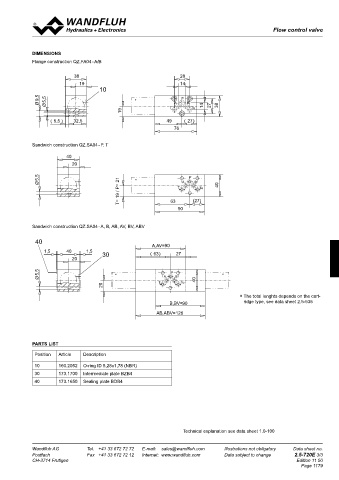
 SCREw-IN CARTRIDGES INSTALLED  DIMENSIONS
 The following screw-in cartridges are used in either the flange body or   Flange construction QZ.FA04 - A/B
 the sandwich body:
 Type   Designation   Data sheet no.  38                        28
 QZ.PM22   flow control valve  19                               14
    •2-way    2.5-535
                                    10
               9,5  5,5                         *                P
               Ø  Ø                                          T  A  B  To  14  27  38
                                            19
                   (  5,5 )  32,5                           49    (  27)
 TYPE CHARTS                                                  76
 Meter-out flow control  Meter-in flow control
            Sandwich construction QZ.SA04 - P, T
                        40
 QZ.FA04-A/B  QZ.SA04-A  QZ.SA04-AV
                          20
               5,5                                                 P
                                           T= 19 / P= 21       T       To
 A  PT  B  A  PT  B  A  PT  B  Ø                *                A   B        40
 QZ.SA04-P  QZ.SA04-B  QZ.SA04-BV                            63      (27)
                                                                90

 A  PT  B  A  PT  B  A  PT  B
            Sandwich construction QZ.SA04 - A, B, AB, AV, BV, ABV
 QZ.SA04-T  QZ.SA04-AB  QZ.SA04-ABV
             40
                                                      A,AV=90
                1,5     40     1,5
 A  PT  B  A  PT  B  A  PT  B  20    30               (  63)   27

               5,5                       *                   P                 *
               Ø                                           A   B      40
                                                         T       To
 By  turning  around  valves  with  meter-out  function,  meter-in  function   20
 can be adchieved:                                                                   ∗  The total lenghts depends on the cart-
 A   turns into BV                                                                     ridge type, see data sheet 2.5-535
 B   turns into AV                                           B,BV= 90
 AB   turns into ABV  38  28
 19
 Valves for flow control are supplied respectively with a sealing plate   14  AB,ABV= 126
 and an intermediate plate.  10
 9,5  5,5  *  P
 Ø  Ø  T  A  B  To  14  27  38
 REMARK!  19  PARTS LIST
 Detailed  performance  data  and  additional  hydraulic
 32,5
 5,5 )
 (
 specifications may by drawn from the data sheets of the   49  (  27)  Position  Article  Description
 corresponding installed pressure relief cartridge.  76
             10       160.2052  O-ring ID 5,28x1,78 (NBR)
 CAUTION!    30       173.1700  Intermediate plate BZB4
 The performace data especially the „pressure-flow-cha-  40  173.1650  Sealing plate BDB4
 racteristic„ on the data sheets of the screw-in catridges
 40
 refere  to  the  screw-in  cartridges  only. The  additional
 20
 pressure drop of the flange body respectivly sandwich
 body must be taken into consideration.
 5,5  *  P
 T= 19 / P= 21  T  To                                            Technical explanation see data sheet 1.0-100
 Ø  A  B  40
 63
 90  (27)
 Wandfluh AG   Tel.  +41 33 672 72 72   E-mail:  sales@wandfluh.com   Illustrations not obligatory   Data sheet no.  Wandfluh AG   Tel.  +41 33 672 72 72   E-mail:  sales@wandfluh.com   Illustrations not obligatory   Data sheet no.
 Postfach   Fax  +41 33 672 72 12   Internet:  www.wandfluh.com   Data subject to change   2.5-720E 2/3  Postfach   Fax  +41 33 672 72 12   Internet:  www.wandfluh.com   Data subject to change   2.5-720E 3/3
 CH-3714 Frutigen                   Edition 11 50  CH-3714 Frutigen                                      Edition 11 50
                                                                                                           Page 1179
 40
 A,AV=90
 1,5  40  1,5  (  63)  27
 20  30

 5,5  *  P  *
 Ø  A  B  40
 T  To
 20


 B,BV= 90
 AB,ABV= 126
   1174   1175   1176   1177   1178   1179   1180   1181   1182   1183   1184