
Page 1141 - Softbound_Edition_19_en
P. 1141
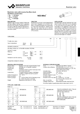
Restrictor valve
 Throttle valves                                                                                  Restrictor valves

 2
 CHARACTERISTICS  Oil viscosity  υ = 30 mm /s  Restrictor valve with reverse free flow check
 ∆p = f (Q)  Pressure loss/flow characteristics  Q = f (n)   Volume flow adjustment characteristics  Sandwich construction
    Restriction in A, B     (Standard ADRA, B, AB)                   ®
            •  Q max   = 10 l/min                        NG3-Mini
            •  Q    = 8 l/min
 p [bar]  Q [l/min]  N max
 30  K0489  80  K0455  ∆p = 20 bar  •  p max   = 315 bar
 25  60  ∆p = 10 bar  DESCRIPTION              FUNCTION                           APPLICATION
 20         Sandwich type one-way restrictor. Fitted with   Free flow in one direction via the spring-loaded   Sandwich type, one-way restrictors are used
 A
 15  A  PT  B  40  A  PT  B  ∆p = 5 bar  PT  B  one way restrictor cartridge with incorporated   check  valve  integrated  in  the  screw-in  car-  where  volume  flows  have  to  be  controlled
 10  20     free flow check. Screw-in cartridge M18x1,5 in   tridge. The opening pressure of the check valve   in one flow direction according to the load.
 5          accordance with ISO 7789 (see data sheet no.   p = 1 bar. In the other direction, with the check   Depending on the application, a distinction is
                                                ö
 0  0       2.4-610). The sandwich plate made of steel is   valve shut, the volume flow can be infinitely   made between restricting the forward flow or
 0  20  40  60  80  100 Q [l/min]  0  0.5  1  1.5  2  2.5  3  3.5  4  4.5  n [-]  zinc-nickel coated.  adjusted via the restrictor section as a function   the return flow. These sandwich valves are
                                               of the pressure.                   particularly suitable for machine tools and also
                                                                                  all kinds of handling operations. Mini-3 oneway
 Caracteristics ADRPT10 can be found on data sheet 2.4-552 (throttle cartridge DNIPM33).
 A  PT  B  A  PT  B                                                               restrictors are used where hydraulic systems
                                                                                  have to be both light and compact.
            TYPE CODE

 DIMENSIONS                                                                DR        S   A03   -       -       #
 ADRP10 #1  ADRA, B, AB10
 54         Throttle check valve
 1  2  3  4  5  48  6  7  8
 40 50
                                   Screw
 ADRP10 / ADRT10  10  A  20,8  PT  B  20  A  PT  B Type of adjustment    A     PT  B  S
                                   Knob
                                              D

 16,8       Sandwich construction
 P  P
 A  P       Mounting interface acc. to Wandfluh standard, NG3-Mini
              A
 1,5
 ∅ 6,5   60   60  ∅ 35  46  T   60   Meter-out   in A   A   in B   B
 A  B  A  A  B  B  Type list / function
 T  To  T  To  To                  in A and B    AB
 A  PT  9,7  B  A  PT   26   B     in A       AV    in B     BV
            Meter-in
 30  10   30   30  10   24.5       in A and B   ABV
 MD=80Nm  MD=80Nm
  90    59.5   66   59.5   Nominal volume flow rates Q    3,2 l/min   3,2
                                 N
 38   38.5    180                          8 l/min            8
  38.5    136   A=137,7
  256.9
 B            B  54
  174.5   B=137,7  Design-Index (Subject to change)
 1  2  3  4  5  6  7  8  48
 49  AB=132                40 50
 ADRP10 / ADRT10  10  20,8        20
            GENERAL SPECIFICATIONS                               HYDRAULIC SPECIFICATIONS
 ADRA10 / ADRB10  Denomination   16,8  Restrictor valve with reverse free flow check  Fluid   Mineraoil, other fluid on request
 ADRAB10  P  Nominal size    NG3-Mini acc. to Wandfluh standard  Contamination efficiency  ISO 4406:1999, class 20/18/14…21/19/15
 P  P
 9,7  A     Construction   1,5  Sandwich                                             (Required filtration grade ß 10…25 ≥ 75)
 A  A            P
 A  B  P  A  B  B  P  A Mounting  B  3 mounting holes for socket head cap screws     refer to data sheet 1.0-50/2
  60   T  ∅ 6,5   60   60  ∅ 35  46  T     M4 or stud screws M4  Viscosity range     12 mm /s…320 mm /s
                                                                                          2
                                                                                                   2
 T  C  To  A  B  T  To   1.5   To  A  26   B  Connections  To  Threaded connection plates, Multi-flange   Fluid temperature   -20...+70 °C
              C
  60                      9,7  subplates, Longitudinal stacking system  Peak pressure   p max  = 315 bar
 30
 30  10   30   T  To  10   24.5   T  To  Ambient temperature   -20…+50 °C  Pressure required to open
 MD=80Nm  MD=80Nm  80  40  Mounting position   any               the check valve     p   = 1 bar
                                                                                      ö
  90    59.5    38.5    180   20  T=120   59.5   10  66  Fastening torque   M = 2,8 Nm (Qual. 8.8) for fastening screws  Nominal volume flow rates Q  = 8 l/min, Q  = 3,2 l/min
                                                                                               N
                                                                                      N
                               D
  38.5    136   20  MD=30Nm  10  40 50 MD= 70Nm  256.9    38   MD=50Nm  38     A=137,7  M = 30 Nm for screw-in cartridge     Q at 10 bar valve pressure loss
                                                                                      N
                               D
 B   49 max.   30  Weight    Depending on the type 0,4…0,5 kg    Max. volume flow    Q   = 10 l/min
  132  B
  174.5      B=137,7                                                                  max
  49 max.    132    5.7
  230 max.                                                       Leakage volume flow   Almost leak free with closed restrictor
  186.7 max.   P  49  AB=132
 PARTS LIST  PARTS LIST  A                                       For further hydraulic specifications refer to data sheet  2.4-610.
 D  B       TYPE LIST / FUNCTION
 ADRA10 / ADRB10  Position  Article  Description  Position  Article  T Description
 ADRAB10  To  Meter-out:  P                         Meter-in:
 30  623.8009  DNIPM33  10  160.2140  O-ring ID 14,00 x 1,78 (NBR)  9,7  A  B         Valves for restricting the meter-in flow are
 P
 P  10  160.2140  O-ring ID 14,00 x 1,78 (NBR)  20  114.1201  Turning knob  66  18  T  DR.SA03-A  DR.SA03-AV  achieved by turning the one-way
 40
  1.5   40  049.2222  Bounded seal ID 22.7 x 30 x 2                                   restrictors (horizontal axis):
 C  A  B  A  B  P=106  C  A  PT  To  A B  PT  B A  PT  A B  PT    B
  60   50  238.5201  Plug DIN 908 M 22 x 1,5                                          A   get   BV
                                                                                         get
                                                                                      B
                                                                                              AV
 T  To  T  To                 DR.SA03-B                               DR.SA03-BV      AB  get   ABV
 Technical explanation see data sheet 1.0-100              22.01.2018 80 BEH  40      Valves for restricting the meter-in flow are

 E                 Gezeichnet  22.02.2018  KL
  Geprüft
 20  10  40 50  20  MD=50Nm  10                 Freigegeben M 1:1.25  22.02.2018  TK T=120  PT  A B  PT  B A  PT  A B  PT  B  supplied with a sealing plate and an
             A
 MD=30Nm  MD= 70Nm   38    49 max.    132   Rev.  Datum  Name Änderungsnr.  Änderungsbeschrieb  Ersetzt durch:   Serie freigegeben Modellreferenz: Doknr. 0167798 / Konfiguration 010  intermediate plate.
           Gewicht
 Drossel-Sandwichventil NG10
           3.830 kg
  Dok.-Nr.
  49 max.    132    5.7    230 max.   ADRP10 #1  Ersatz für:   0231117  Format  30 DR.SA03-AB  DR.SA03-ABV
           A2
  186.7 max.   Dokument darf ohne schriftliche Einwilligung weder kopiert,  Art.-Nr.  DB 2.4-770  Revision P
            00
 verwertet noch an Dritte weitergegeben werden.
 Zuwiderhandlung ist strafbar und wird gerichtlich verfolgt.
 1  2  3  4  5  C:\00_Wandfluh\Verkauf\Dokumentation\Reg2.4\DB 2.4-730\0231117  Blatt 1 von 1
       A     A  B  PT      A B  PT     B A    PT     A B   PT     B
 D
    T
 Wandfluh AG   Tel.  +41 33 672 72 72   E-mail:  sales@wandfluh.com   Illustrations not obligatory   Data sheet no.   Wandfluh AG   Tel.  +41 33 672 72 72   E-mail:  sales@wandfluh.com   Illustrations not obligatory   Data sheet no.
                 To
 Postfach   Fax  +41 33 672 72 12   Internet:  www.wandfluh.com   Data subject to change   2.4-770E 2/2   Postfach   Fax  +41 33 672 72 12   Internet:  www.wandfluh.com   Data subject to change   2.4-800E 1/2
 CH-3714 Frutigen                   Edition 21 31  CH-3714 Frutigen                                      Edition 21 31
       40       66      18                                                                                 Page 1141
           P=106
                Gezeichnet  22.01.2018  BEH
 E                 Geprüft  22.02.2018  KL
                Freigegeben  22.02.2018  TK
 Rev.  Datum  Name Änderungsnr.  Änderungsbeschrieb  M 1:1.25  Serie freigegeben Modellreferenz: Doknr. 0167798 / Konfiguration 010
 Gewicht
 Drossel-Sandwichventil NG10  Ersetzt durch:   3.830 kg
 Ersatz für:
 ADRP10 #1  Dok.-Nr.  0231117  Format  20          20
 A2
 Dokument darf ohne schriftliche Einwilligung weder kopiert,  Art.-Nr.  Revision  20  20
 verwertet noch an Dritte weitergegeben werden.  DB 2.4-770  00  13  13  10  10
 Zuwiderhandlung ist strafbar und wird gerichtlich verfolgt.  10  10
 1  2  3  4  5  C:\00_Wandfluh\Verkauf\Dokumentation\Reg2.4\DB 2.4-730\0231117  Blatt 1 von 1
              ∗            ∗           P            P          ∗             ∗
                                   A      B      A     B
                                                11  21       11  21       30           30
                                  T        To  T         To            15            15
 ∅ 4,2  30  ∅ 4,2  30  B=3,7  B=3,7   96           96     A=3,7        A=3,7
                              DR.SA03-A    DR.SA03-A
                                          DR.SA03-B    DR.SA03-B
                                    DR.SA03-AB   DR.SA03-AB
 40  4030     30
                                       P             P
              ∗            ∗       A      B      A     B        ∗            ∗
                                  T        To  T         To
 1,2  30  1,2 1,2  30  1,2
                             DR.SA03-AV   DR.SA03-AV
                                          DR.SA03-BV   DR.SA03-BV
                                   DR.SA03-ABV   DR.SA03-ABV