
Page 1096 - Softbound_Edition_19_en
P. 1096
Proportional
Proportional pressure relief valve
Proportional pressure relief valve pressure relief valves
10 21,5 19
20
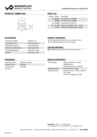
HYDRAULIC CONNECTION PARTS LIST Proportional pressure relief valve 17,8
22
Position Article Description Flange and sandwich construction NG6 T
T
28 10 160.2052 O-ring ID 5,28 x 1,78 (NBR) • p = 400 bar ♦ 5,5 A B ∗ ISO 4401-03 ♦ ∗ 31 A B 21 32,5 ∗ 45
♦
45
14 max Ø G1/4"
160.6052 O-ring ID 5,28 x 1,78 (FKM) 18 P 17,5 22,5 P 22,5
P 20 238.2406 Screw plug VSTI G1/4"-ED 12 40 36 68 A= 102
50 173.1450 Distance plate BDP4 / 12 (h = 12 mm) 52 104 B= 102
A B AB= 140
14 27 173.1451 Distance plate BDP4 / 20 (h = 20 mm)
T T0
T
♦ ♦ A B ∗
ACCESSORIES SURFACE TREATMENT DESCRIPTION P FUNCTION APPLICATION
Proportional amplifier Register 1.13 ◆ The flange body is painted with a two component paint Pilot and direct operated proportional pres- By adjusting the electric current to the pro- The valves have their applications in hydraulic
◆ The sandwich bodies are zinc-nickel coated sure relief valves NG6. Flange and sandwich portional solenoid the operating pressure in systems in which the pressure frequently has to
Threaded subplates Data sheet 2.9-10
construction according to ISO 4401-03 with 4 hydraulic systems is limited by reliefing the be changed. The facility for remote control and
Multi-station subplates Data sheet 2.9-50 ports. Incorporated are proportional pressure fluid from the protected lines P, A, B or A and signal processing from process control systems
Module type manifold blocks Data sheet 2.9-90 SEALING MATERIAL relief cartridges size M22x1,5 according to ISO B to the return / tank line T. Back pressure in T enable economical solutions to problems with
7789. The flange and sandwich bodies made
influences the pressure in the reliefed pressure
repeatable sequences.
Technical explanations Data sheet 1.0-100 NBR or FKM (Viton) as standard, choice in the type code of steel are phosphatized. lines. This proportional pressure relief valves
Filtration Data sheet 1.0-50 are adjustable very sensitivly. To control the
valve proportional amplifiers are available from
Wandfluh (see register 1.13).
TYPE CODE
STANDARDS INSTALLATION NOTES B A06 - - #
Mounting interface Wandfluh standard Mounting type Flange or sandwich mounting Pressure relief valve
Protection class EN 60 529 3 fixing holes for
Contamination ISO 4406 socket head screws or studs M5 2nd and 3rd digit position of the designation od the built-in cartridge
efficiency Mounting position Any, preferably horizontal Flange construction F
Tightening torque Fixing screws M = 5,2 Nm (quality 8.8, Sandwich construction S
D
zinc coated) International standard interface ISO, NG6
Screw-in cartridge M = 60 Nm Type list / Function flange construction sandwich construction
D
in P P in P P
in A A
in B B
in A and B AB
Nominal pressure range, nominal voltage, etc., of the built-in cartridge
Design-Index (Subject to change)
Examples: B V P F A06 – P – 20 – G24 / WD – HB4,5
B D B S A06 – A – 100 - G12 / L15
B N I S A06 – B – 200 – G24 / KD – D1
B V P S A06 – AB – 350 – G12 / ME A1 R1
TYPE LIST / FUNCTION
Flange construction: Sandwich construction:
B..FA06-P B..SA06 - P B..SA06 - A B..SA06 - B B..SA06 - AB
Wandfluh AG Postfach CH-3714 Frutigen
Tel. +41 33 672 72 72 Fax +41 33 672 72 12 sales@wandfluh.com
Wandfluh AG Tel. +41 33 672 72 72 E-mail: sales@wandfluh.com Illustrations not obligatory Data sheet no.
www.wandfluh.com Illustrations are not binding Data subject to change 4/4 Edition: 21 11 2.3-720 E Postfach Fax +41 33 672 72 12 Internet: www.wandfluh.com Data subject to change 2.3-740E 1/2
CH-3714 Frutigen Edition 14 02
Page 1096