Page 1022 - Softbound_Edition_19_en
P. 1022
Proportional pressure reducing valve
Proportional pressure reducing valve Proportional pressure reducing valve
TYPE CODE PERFORMANCE SPECIFICATIONS
2
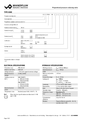
M G B PM16 - 100 - / / - # Oil viscosity u = 30 mm /s
Pressure reducing valve p = f (Q) Pressure volume flow characteristics p = f (n) Pressure adjustment characteristics
red
red
Direct operated Maximal adjustable pressure Measured at Q = 0 l/min (static)
p [bar] **Slightly increased hysteresis
Proportional, explosion proof execution Ex d 120 K1154 p [bar]
100 100 K1153
Screw-in cartridge M16 x 1,5
80 80
Nominal pressure range p 100 bar 60 60
N red
40
Nominal voltage U 12 VDC G12 20 40
N
24 VDC G24 0 20 **
6 4 2 0 2 4 6
Ambient temperature up to: A T Q [l/min] P A 0 0 10 20 30 40 50 60 70 80 90 100 l [%]
Nominal power P 15 W L15 70 °C
N
17 W L17 70 °C (only UL / CSA)
Certification ATEX, IECEx, EAC, DIMENSIONS HYDRAULIC CONNECTION
CCC UL / CSA UL Cavity drawing according to Wandfluh standard
Australia AU MA MA
Sealing material NBR 110 M16x1.5
FKM (Viton) D1
Options without s30 (3)
amplifier M248 70.8
93.3 M16x1.5
System pressure max. 210 bar 15 (2)
System pressure max. 350 bar Z406 MD=5.5Nm (3) (2)
(1)
Design index (subject to change) (1)
2.3-608 22.5 (1)
12
ELECTRICAL SPECIFICATIONS HYDRAULIC SPECIFICATIONS MD=9Nm 17 18 10 18 50 60 80 Attention! For detailed cavity drawing and cavity tools see data
sheet 2.13-1051
Protection class IP65 / 66 / 67 Working pressure p = 210 bar (350 bar) 60
max
Relative duty factor 100 % DF Nominal pressure p N red = 100 bar 88.6 27.1
Voltage tolerance ± 10 % with regard to nominal voltage range 122.6
Standard nominal 12 VDC, 24 VDC Minimum adjustable < 0,5 bar
voltage pressure PARTS LIST ACCESSORIES
Limiting current at L15 / 17, 50 °C Volume flow range Q = 0…6 l/min Position Article Description Proportional amplifier Register 1.13
50 °C I = 950 mA (12 VDC) Leakage oil p = 160 bar
G
sys
I = 450 mA (24 VDC) p = 0 bar: < 15 ml/min 10 263.6... Solenoid coil MK.45 / 18 x 60 Technical explanations Data sheet 1.0-100
red
G
L15 / 17, 70 °C p = 0,5 x p N red : < 60 ml/min 12 154.2603 Knurled nut Ex M18 x 1,5 x 18 Filtration Data sheet 1.0-50
red
I = 910 mA (12 VDC) Hysteresis ≤ 4 % at optimal dither signal 15 253.8000 Manual override HB4,5
G
I = 420 mA (24 VDC)
G Repeatability ≤ 1 % at optimal dither signal 17 160.2187 O-ring ID 18,72 x 2,62 (NBR)
Standard nominal 15 W, 17 W Fluid Mineral oil, other fluid on request 18 160.2170 O-ring ID 17,17 x 1,78 (NBR)
power Viscosity range 12 mm /s…320 mm /s
2
2
Temperature class Nominal power 15 W / 17 W: T1…T4 Temperature range Operation as T4 50 160.2140 O-ring ID 14,00 x 1,78 (NBR) MANUAL OVERRIDE
160.8140
O-ring ID 14,00 x 1,78 (FKM)
Note! Other electrical specifications see data sheet 1.1-183 fluid NBR -25…+70 °C (L15 / L17) 60 160.2093 O-ring ID 9,25 x 1,78 (NBR) HB4,5 as standard
and 1.1-184 FKM -20…+70 °C (L15 / L17) 160.8092 O-ring ID 9,25 x 1,78 (FKM)
Contamination Class 18 / 16 / 13 80 160.2076 O-ring ID 7,65 x 1,78 (NBR)
efficiency 160.8076 O-ring ID 7,65 x 1,78 (FKM)
Filtration Required filtration grade ß 6…10 ≥ 75,
see data sheet 1.0-50 110 111.1080 Cable gland M20 x 1,5
www.wandfluh.com Illustrations are not binding Data subject to change 2/4 Edition: 21 21 2.3-608 E www.wandfluh.com Illustrations are not binding Data subject to change 3/4 Edition: 21 21 2.3-608 E
Page 1022

