
Page 929 - Softbound_Edition_19_en
P. 929
54
48
32,5 10 20,8 20
P
1,5 G1/4"
10,5 6,5 26,5 A B
Pressure reducing valve
Ø Ø ∗ 46 60 Pressure reducing valves Pressure reducing valves
39 T To 33,5
6 44 95 45
CHARACTERISTICS oil viscosity υ = 30 mm /s 140 SCREw-IN CARTRIDGES INSTALLED Pressure reducing valve
2
50
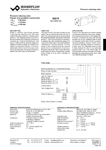
∆p = f (Q) Pressure loss/flow characteristics The following screw-in cartridges are used in either the flange body or Flange- and sandwich construction NG10
the sandwich body:
32
over non-retourn valve • Q = 80 l/min ISO 4401-05
p [bar] Type Designation Data sheet no. • p max = 315 bar
4 K0337 P MV.PM22 Pressure reducing valve • p max = 160 bar
G1/4"
A B • pilot operated 2.2-530 N red max
3 6,5 Ø 40 ∗ T To 42,5 60
2 DESCRIPTION FUNCTION APPLICATION
50 95 45 Flange or sandwich type directly operated The spool is held in the home position by the Pressure reducing valves are used for keeping
1 140 REMARK! 3-way pressure reducing valve. The valve spring. The connection to the consumer is fully the pressure constant in a consumer, irrespec-
18 Detailed performance data and additional hydraulic
0 16 specifications may by drawn from the data sheets of the reduces the inlet pressure to a preset output open. The reduced pressure can be adjusted at tive of pressure fluctuations on the supply side.
0 20 40 60 80 Q [l/min] corresponding installed cartridge. pressure. The integrated pressure relief func- the adjustment spindle, irrespective of the inlet If several consumers are used, the reduced
P tion prevents the reduced pressure from being pressure. If the reduced pressure increases, pressure can be set individually with the aid if
G1/4" exceeded as a result of external forces. Two it displaces the valve towards the spring. The one pressure control valve for each consumer.
A B types of setting and four pressure stages are volume flow at the valve inlet is then throttled, Generally speaking, pressure control valves
60
6,5 ∗ 42CAUTION!
Ø 40 The performace data especially the „pressure-flow-cha- available. A pressure gauge connection is pro- controlling the reduced pressure. If forces are used for reducing a hydraulic pressure to
T To
racteristic„ on the data sheets of the screw-in catridges vided in the reduced connection. In the sand- acting on the consumer allow the reduced a lower level. The integrated pressure relief
refere to the screw-in cartridges only. The additional press- wiches with control in A or B line by-pass check pressure to be increased above the set value, function obviates the need for any additional
50 93,5 46,5 ure drop of the flange body respectivly sandwich body must valves are integrated. The flange valve body is the spool is displaced until the valve inlet closes pressure relief valve in the reduced pipe. Di-
140 be taken into consideration. painted, the other parts are phosphated. and the tank port opens. The pressure increase rectly operated pressure reducing valves also
is then limited to a low value, controlled by keep the reduced pressure stable, even under
the spring. very difficult operating conditions.
TYPES / DIMENSIONS
Flange Sandwich MV.FA10-P/A
MV.FA10-P/A MV.SA10-P T B 10 54 20
A
P red
48
32,5 20,8 TYPE CODE
A DRV d 10 / #
P
1,5 G1/4" Mounting interface acc. to Wandfluh standard,
A P T A P T B 10,5 6,5 26,5 A B
Ø Ø 39 ∗ 46 60 Pressure reducing valve
MV.SA10-A T To 33,5
A P T B Direct operated
6 44 95 45 Type list / function
50 140 Flange design N
Sandwich design, P in P
red
32 MV.SA10-P Sandwich design, P in A A
red
A red P T B Sandwich design, P in B B
red
P G1/4" Interface NG10
MV.SA10-B A B
A P T B 6,5 Ø 40 ∗ T To 42,5 60 Type of adjustment Key D
Control knob
Cover H
50 95 45 Pressure range p N red 20 bar 20
140 50 bar 50
18 100 bar 100
A P T B red 16 MV.SA10-A 160 bar 160
P Design-Index (Subject to change)
G1/4"
A B
6,5 ∗ 60
Ø 40 42
T To GENERAL SPECIFICATIONS HYDRAULIC SPECIFICATIONS
Description Direct operated pressure control valve Fluid Mineral oil, other fluid on request
50 93,5 46,5 Nominal size NG10 acc. to ISO 4401-05 Contamination efficiency ISO 4406:1999, class 18/16/13
140 Construction Flange- or sandwich (Required filtration grade ß 6…10≥75)
Mounting 4 mounting holes for zyl. screws M6 or refer to data sheet 1.0-50/2
2
2
PARTS LIST For sandwich red.pressure in B cartridge is located on B-side. double ended screws M6 Viscosity range 12 mm /s…320 mm /s
* The total lengths depends on the cartridge type, Connection Threaded connection plates Fluid temperature -20…+70 °C
Position Article Description see data sheet 2.2-530. Multi-flange subplates Peak pressure p p max = 315 bar
Longitudinal stacking system
= 50 bar
Tank load in connection T
T max
P red
A
10 160.2140 O-ring ID 14,00x1,78 ACCESSORIES T B Reg. 2.9 Ambient temperature -20…+50 °C Nominal pressure p N red = 20 bar, p N red = 100 bar
= 50 bar, p
any
Mounting position
= 160 bar
p
Threaded connection plate and multi-flange subplates
20 238.2406 Plug VSTI G1/4"-ED Bypass non-return valve BDRVP4 Fastening torque M = 9,5 Nm (quality 8.8) Opening pressure p = 0,2 bar N red
N red
D
Weight m = 4,2 kg to non-return valve ö
Volume flow Q = 0…80 l/min
A P T A P T B
Technical explanation see data sheet 1.0-100 A P T B
Wandfluh AG Tel. +41 33 672 72 72 E-mail: sales@wandfluh.com Illustrations not obligatory Data sheet no. Wandfluh AG Tel. +41 33 672 72 72 E-mail: sales@wandfluh.com Illustrations not obligatory Data sheet no.
Postfach Fax +41 33 672 72 12 Internet: www.wandfluh.com Data subject to change 2.2-660E 2/2 Postfach Fax +41 33 672 72 12 Internet: www.wandfluh.com Data subject to change 2.2-670E 1/2
CH-3714 Frutigen Edition 05 04 CH-3714 Frutigen Edition 21 30
A red P T B Page 929
A P T B
A P T B red