
Page 831 - Softbound_Edition_19_en
P. 831
Pressure relief valve
Pressure relief valve
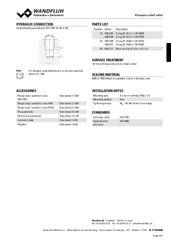
HYDRAULIC CONNECTION PARTS LIST
Cavity drawing according to ISO 7789–22–02–0–98 Position Article Description
10 160.2188 O-ring ID 18,77 x 1,78 (NBR)
M22x1.5
160.6188 O-ring ID 18,77 x 1,78 (FKM)
20 160.2140 O-ring ID 14,00 x 1,78 (NBR)
160.6141 O-ring ID 14,00 x 1,78 (FKM)
(2) 30 049.3177 Back-up ring rd 14,6 x 17,5 x 1,4
(1)
SURFACE TREATMENT
(1) ◆ The cartridge body is zinc-nickel coated
Note! For detailed cavity drawing and cavity tools see data
sheet 2.13-1003 SEALING MATERIAL
NBR or FKM (Viton) as standard, choice in the type code
ACCESSORIES INSTALLATION NOTES
Flange body / sandwich plate Data sheet 2.1-620 Mounting type Screw-in cartridge M22 x 1,5
NG4-Mini Mounting position Any
Flange body / sandwich plate NG6 Data sheet 2.1-640 Tightening torque M = 60 Nm Screw-in cartridge
D
Flange body / sandwich plate NG10 Data sheet 2.1-660
Threaded body Data sheet 2.9-200 STANDARDS
Technical explanations Data sheet 1.0-100 Cartridge cavity ISO 7789
Hydraulic fluids Data sheet 1.0-50 Contamination ISO 4406
Filtration Data sheet 1.0-50 efficiency
Wandfluh AG Postfach CH-3714 Frutigen
Tel. +41 33 672 72 72 Fax +41 33 672 72 12 sales@wandfluh.com
www.wandfluh.com Illustrations are not binding Data subject to change 3/3 Edition: 18 44 2.1-539 E
Page 831