
Page 821 - Softbound_Edition_19_en
P. 821
Pressure relief valve
Pressure relief valves
Safety valve
EU - type tested M22x1,5
Pressure Equipment Directive 2014/68/EU
• Pilot operated ISO 7789
• Q max = 30 l/min
• p = 350 bar 1250
N max
DESCRIPTION FUNCTION APPLICATION
Pilot operated pressure relief valve as screw- When reaching the set and locked seal re- For the protection of the maximum permis-
in cartridge with thread M22x1,5 for cavity sponse pressure, the main spool opens and sible operating pressure in hydraulic systems
according to ISO 7789. The valve is designed connects the protected line with the return with pressure accumulators, resp. pressure
according to AD-2000 and EU-type tested line to the tank. These pressure relief valves reservoirs by the flowing out of the oil from
in accordance with the Pressure Equipment consist of a main and a pilot operation system the protected oil line P (1) to the tank line T
Directive 2014/68/EU. As standard versions, integrated into the cartridge. The pilot opera- (2). The screw-in cartridge is very suitable
the following preferential response pressures tion is a direct operated pressure relief valve for mounting in control blocks and is built into
are available: 100, 140, 250, 330 and 350 bar. which acts on the main system. These safety the Wandfluh hydraulics NG6 and NG10 as a
Apart from this, within the range of 50 – 350 valves are suitable for the protection of hy- functional element in sandwich style plates
bar response pressures can be freely selec- draulic systems with pressure accumulators, (vertical combination) and flange-mounted
ted. The cartridge body and the cover made of resp. pressure reservoirs. The very limited valves (please refer to the separate data
steel are zinc coated and therefore protected play of the hardened spool results in a limited sheets in register 2.1). Stepped tools are avai-
against rust and the blue locking seal made oil leakage. lable for making the receptacle bores in steel
of plastic provide this quality product with a and aluminium (hire or purchase). Please refer
clean design. to the data sheets in register 2.13. Attention:
The banking-up pressure in the tank line for
Q must amount to a maximum of 3 bar.
max
CONTENT TYPE CODE
B V T PM22 - - #
GENERAL SPECIFICATIONS ...................1 Pressure relief valve
HYDRAULIC SPECIFICATIONS ...............1 Pilot operated
EU - Type tested in accordance with PED 2014/68/EU
SYMBOL ......................................................1
Screw-in cartridge M22x1,5
CARACTERISTICS ....................................2 Response pressure range
50…< 160 bar A
DIMENSIONS .............................................2 160…< 260 bar B
260… 350 bar C
PARTS LIST ................................................2 Response pressure p in bar
A
ACCESSORIES ..........................................2 Design-Index (Subject to change)
GENERAL SPECIFICATIONS HYDRAULIC SPECIFICATIONS
Description EU - type tested safety valve Hydraulic fluid Mineral oils of fluid group 2,
Construction Screw-in cartridge for cavity acc. to ISO 7789 other media on request
Mounting Screw thread M22x1,5 Contamination efficiency ISO 4406:1999, class 18/16/13
Ambient temperature -20…+50 °C (Required filtration grade ß 6…10≥75)
Mounting position any refer to data sheet 1.0-50/2
Fastening M = 50 Nm Viscosity range 12 mm /s…320 mm /s
2
2
D
Weight m = 0,20 kg Fluid temperature Standard: -20…+70 °C
Basic material The material of the hydraulic block must be ATEX IIC, T6: -20 °C…+40 °C
chosen in accordance to the pressure equip- ATEX IIC, T4: -20 °C…+70 °C
ment directive (PED) and general safety Ad. volume flow Q max = 30 l/min
considerations. In case of pressure above Leakage volume flow See curve
160 bar the manufacturer advises steel with Preferential response 100 bar ٭
a tensile strength of at least 330 N/mm . pressure p 140 bar ٭
2
A
250 bar ٭
330 bar ٭
350 bar ٭
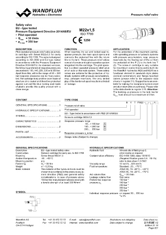
SYMBOL
Individual response pressure on request 50… 350 bar
P(1) ٭± 3%
T(2)
Wandfluh AG Tel. +41 33 672 72 72 E-mail: sales@wandfluh.com Illustrations not obligatory Data sheet no.
Postfach Fax +41 33 672 72 12 Internet: www.wandfluh.com Data subject to change 2.1-532E 1/2
CH-3714 Frutigen Edition 21 18
ca.10 Page 821
46,8
s27
Ø30
20
M 22x1,5
38,5 30
2(T)
10
1(P)
M22x1,5
min Ø 6mm
T (2)
min Ø 6mm
P (1)