
Page 801 - Softbound_Edition_19_en
P. 801
58,2 20 62,2 20 10 10 s32 s36 M33x2 M33x2 (2)
2(P) (1)
22,5
Screw-in cartridge
15 Info screw-in cartridges Screw-in cartridges
1(T)
2,2
20 OVERVIEW PROPORTIONAL FLOW CONTROL VALVES 50,9 Types of adjustment
92
142,9 for manual screw-in cartridges
15 Function 17 Size 18 50 50 70 60 1 5 /16"-12 UN M33x2 M42x2 Ø 26 Ø 22
M18x1.5
M22x1.5
7 /8"-14 UNF
70
17
18
82,5
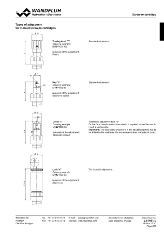
6,2 2-way Type QZPPM18 50,55 60 QNPPM22 QNPPU16 QNPPM33 QNPPM42 Turning knob "D" Standard adjustment
Data sheet 2.6-610 2.6-631 2.6-675 2.6-651 2.6-690 Ordering example:
133,05 BVDPM22-350
58,2 20 10 Type s30 M22x1,5 QNPPM22-../ME QNPPM33-../ME Materials of the adjustment:
X + 5
1 2 Data sheet 2.6-633 2.6-659 X Plastic
(3) (2)
Type 1 2 QNBPM22 QNBPM33
(1)
18,7 Data sheet 2.6-634 2.6-655
Cavity 2.13-1038 2.13-1008 2.13-1049 2.13-1005 2.13-1050
15 Ø 27
2-way seat-tight Type QSPPU10 QSPPM33 Ø 17
6,2 78,4 60,5 s4
2 Data sheet 2 2.6-638 90 2.6-661
138,9
Key "S" Standard adjustment
17 18 50 60 80 70 s13 Ordering example:
1 Cavity 2.13-1058 2.13-1005 MVSPM22-63
X
3-way Type QDPPM22 QDPPU16 QDPPM33 QDPPM42 X - 12 Materials of the adjustment:
Steel zinc-coated
Data sheet 2.6-644 2.6-670 2.6-666 2.6-695
Type QDPPM22-../ME QDPPM33-../ME
1 3
1
Data sheet 1 3 2.6-647 2.6-668
2 Ø 40
Type ● QDBPM22 Ø 23
Data sheet 2 2.6-648 Ø 3
Cavity 2.13-1004 2.13-1046 2.13-1040 2.13-1047 Cover "A" Addition to adjustment type "S"
Ordering example: On the face there is a small bore which, if required, allows the user to
insert a sealing wire.
MVAPM22-63
X + 8
Execution with integrated electronics ● Execution Ex d X - 4 Materials of the adjustment: Important: The necessary cross bore in the adjusting spindle has to
be drilled by the customer. We recommend a bore diameter of 2 mm.
Steel zinc-coated
Ø 30
Lock "K" The lockable adjustment
Ordering example:
MVKPM22-63
Materials of the adjustment:
X + 18 Aluminium
Wandfluh AG Tel. +41 33 672 72 72 E-mail: sales@wandfluh.com Illustrations not obligatory Data sheet no. Wandfluh AG Tel. +41 33 672 72 72 E-mail: sales@wandfluh.com Illustrations not obligatory Data sheet no.
Postfach Fax +41 33 672 72 12 Internet: www.wandfluh.com Data subject to change 2.0-20E 6/6 Postfach Fax +41 33 672 72 12 Internet: www.wandfluh.com Data subject to change 2.0-50E 1/2
CH-3714 Frutigen Edition 21 27 CH-3714 Frutigen Edition 15 10
Page 801