
Page 779 - Softbound_Edition_19_en
P. 779
4
3
5
2
1
A
7.4
60
30
B
68
118
119
X1 6 101.6 7 X2 8 A B
36
C C
1 7 12 1 6
A B
101.6 6 1 12 7
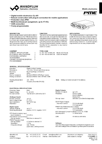
Mobile electronics
Mobile electronics I/O Module CL-450 Mobile electronics I/O Module CL-451
D D
X3 (C), 18-pole, Connector C-coded X4 (D), 18-pole, Connector D-coded • Digital mobile electronics CL-451 75 Programmable Mobile Electronics (2 : 1)
• Robust construction with plug-in connection for mobile applications
Pin Function Pin Function 7.4
• Protection class IP68 133 143
1* Input #27 STB / STG 1* Input #40 STB / STG • Multi-functional pin assignment, up to 17 I/Os
Output #17 DOUT(+) / PWM(+) / ECC Output #25 DOUT(+) / PWM(+) / ECC • CAN connection
2* Input #28 STB / STG 2* Input #41 STB / STG • Freely programmable E Gezeichnet 30.03.2016 BEH E
Output #18 DOUT(+) / PWM(+) / ECC Output #26 DOUT(+) / PWM(+) / ECC Rev. Datum Name Änderungsnr. Änderungsbeschrieb Geprüft M 1:1 04.05.2016 FA TK
04.05.2016
Freigegeben
Serie freigegeben
3* Input #29 STB / STG 3* Input #42 STB / STG 30 Mobilelektronik I/O Modul Ersetzt durch: 0.175 kg
Gewicht
Ersatz für:
Dok.-Nr.
Format
Output #19 DOUT(+) / PWM(+) / ECC Output #27 DOUT(+) / PWM(+) / ECC CL-451 Dokument darf ohne schriftliche Einwilligung weder kopiert, Art.-Nr. 0195273 Revision
A2
00
4* Input #30 STB / STG 4* Input #43 STB / STG 1 2 3 4 5 verwertet noch an Dritte weitergegeben werden. DB 1.13-290 Blatt 1 von 1
Zuwiderhandlung ist strafbar und wird gerichtlich verfolgt.
C:\00_Wandfluh\Verkauf\Dokumentation\Reg1.13\0195273
Output #20 DOUT(+) / PWM(+) / ECC Output #28 DOUT(+) / PWM(+) / ECC DESCRIPTION FUNCTION APPLICATION
5 BAT(-) Module 5 BAT(-) Module Microcontroller based control with multifunc- The control can be used and programmed as a This mobile electronics is used mainly in the
6 BAT(+) Outputs 17-24 6 BAT(+) Outputs 25-33 tional inputs/outputs of the PME devices family stand alone unit, or as part of a distributed, de- mobile field because of the compact construc-
7 CAN3-H 7* Input #44 STB / STG (Programmable Mobile Electronics). Delivered centralised system architecture. The variably tion, protection class IP67 as well as the ex-
8 CAN3-L Output #29 DOUT(+) / PWM(+) / ECC in a robust and compact plastic housing, it is usable inputs and outputs enable reading and tensive operating temperature range and the
9* Input #31 STB / STG 8 Input #45 STB designed for the hard use in working devices controlling sensors and actuators of all kinds. selected plug connection. Customer-specific
Output #21 DOUT(+) / PWM(+) / ECC 9* Input #46 STB / STG and is perfectly suitable for various open loop The free programmability enables maximum requirements can be easily implemented.
10* Input #32 STB / STG Output #30 DOUT(+) / PWM(+) / ECC and closed loop control tasks. flexibility for the adaptation to any desired
Output #22 DOUT(+) / PWM(+) / ECC 10* Input #47 STB / STG machine function.
11 Input #33 STB Output #31 DOUT(+) / PWM(+) / ECC
12 Return(-) Outputs 23 - 24 11 Input #48 STB
13* Input #34 STB / STG 12 Return(-) Outputs 32 - 33 CONTENT TYPE CODE
Output #23 DOUT(+) / PWM(+) / CC 13* Input #49 STB / STG GENERAL SPECIFICATIONS 1 CL-451-100-10-WAG-00 Master I/O Module
14* Input #35 STB / STG Output #32 DOUT(+) / PWM(+) / CC ELECTRICAL SPECIFICATIONS 1 CL-451-100-20-WAG-00 Client I/O Module
Output #24 DOUT(+) / PWM(+) / CC 14* Input #50 STB / STG DIMENSIONS, ASSEMBLY 2
15 Input #36 STB Output #33 DOUT(+) / PWM(+) / CC ACCESSORIES 2
16 Input #37 STB 15 Input #51 STB CONNECTOR WIRING DIAGRAM / 3
17 Input #38 STB 16 Input #52 STB PIN ASSIGNMENT
18 Input #39 STB 17 Input #53 STB
18 Input #54 STB
GENERAL SPECIFICATIONS
X5 (E), 18-pole, Connector E-coded Execution Plastic molded housing
Dimensions 119 x 36 x 133 mm (see Dimensions)
Pin Function Mounting Mounting flange, screwed on
Weight 250 g
1 Input #55 VTD1(0-5.5V) / VTD2(0-35V) Device receptacle Deutsch DTM04-12PA/B pin header
2 Input #56 VTD1(0-5.5V) / VTD2(0-35V) Mating connectors Deutsch DTM06-12SA / DTM06-12SB
3 Input #57 VTD1(0-5.5V) / VTD2(0-35V)
4 Input #58 VTD1(0-5.5V) / VTD2(0-35V) Working temperature -40…+70°C Note Mating connector not part of the delivery
5 5VDC Sensor Supply (250mA) MTBF 79 years (Telcordia SR-332)
6 5VDC Sensor Supply (250mA)
7 Input #61 STB
8 Input #62 STB
9 Input #63 STB / STG / VTD(0-5.5V) / RTD(500Ohm) / 20mA ELECTRICAL SPECIFICATIONS
10 Input #64 STB / STG / VTD(0-5.5V) / RTD(500Ohm) / 20mA
11 Input #65 STB / STG / VTD(0-5.5V) / FREQ / Count / PWM / Protection Class IP68 Digital Outputs
Encoder(1A) Supply Voltage 8…32 VDC Number of outputs up to 16
12 Input #66 STB / STG / VTD(0-5.5V) / FREQ / Count / PWM / No-load current 152 mA at 8 V, 259 mA at 32 V Protection Short to GND
Encoder(1B) Short to Battery
13 Input #67 STB / STG / VTD(0-5.5V) / RTD(500Ohm) / 20mA DOUT = digital output Analogue Inputs Overcurrent
14 Input #68 STB / STG / VTD(0-5.5V) / RTD(2kOhm) / 20mA CC = constant current Number of inputs up to 5 Pull-up / down 560 Ohm / 2.6 kOhm for diagnostics
15 Input #69 STB / STG / VTD(0-5.5V) / FREQ / Count / PWM / ECC = estimated current feedback Input voltage range 0…5.5 V
Encoder(2A) PWM = pulse with modulation Input resistance 58.7 kOhm typ. DOUT Digital Outputs
16 Input #70 STB / STG / VTD(0-5.5V) / RTD(2kOhm) / 20mA VTD = analog input Resolution 12 bit maximum current 3.0 A (individual)
17 Input #71 STB / STG / VTD(0-5.5V) / RTD(2kOhm) / 20mA STG = switch to ground (input) 2.0 A (grouped)
18 Input #72 STB / STG / VTD(0-5.5V) / FREQ / Count / PWM / STB = switch to battery (input) Digital Inputs PWM Pulse Width Modulation Output
Encoder(2B) FREQ = frequency input number of inputs up to 17 maximum current 3.0 A (individual)
Switching threshold positive >3.5 V, negative <1.0 V 1.5 A (grouped)
ECC Estimated Current Feedback, 0.2-3.7 A / 10 Bit
STB Switch to battery input Accuracy ECC +/- 50mA at 2A
*) Special requirements: Bank 1: X1 (A) pin 1 / pin 2 / pin 13 / pin 14 Input resistance 2.6 kOhm
The input and output pins are linked together in a connector strip Bank 2: X2 (B) pin 1 / pin 2 / pin 13 / pin 14 STG Switch To Ground input CAN 40 kbit/s to 500 kbit/s
(Bank). All pins within one connector strip have to be configured in the Bank 3: X3 (C) pin 1 / pin 2 / pin 13 / pin 14 Pull-up resistor 560 Ohm to internal 5 V
same way. Either all pins as outputs, or as STB/STG inputs. Bank 4: X4 (D) pin 1 / pin 2 / pin 13 / pin 14 FREQ Frequency Input
Bank 5: X1 (A) pin 3 / pin 4 / pin 9 / pin 10 Pull-up resistor 4.7 kOhm to internal 5 V
X2 (B) pin 3 / pin 4 / pin 9 / pin 10 Resolution < 5 Hz Software
X3 (C) pin 3 / pin 4 / pin 9 / pin 10 Frequency Range max. 10 kHz Apart from the programming tools, a software for diagnostics and
X4 (D) pin 3 / pin 4 / pin 7 / pin 9 / pin 10 (open drain, sinking sensor) error eliminating for the commissioning of the system is available.
Wandfluh AG Tel. +41 33 672 72 72 E-mail: sales@wandfluh.com Illustrations not obligatory Data sheet no. Wandfluh AG Tel. +41 33 672 72 72 E-mail: sales@wandfluh.com Illustrations not obligatory Data sheet no.
Postfach Fax +41 33 672 72 12 Internet: www.wandfluh.com Data subject to change 1.13-285E 4/4 Postfach Fax +41 33 672 72 12 Internet: www.wandfluh.com Data subject to change 1.13-290E 1/3
CH-3714 Frutigen Edition 19 18 CH-3714 Frutigen Edition 19 18
Page 779