Page 653 - Softbound_Edition_19_en
P. 653

Poppet valve
                                                                                                      Poppet valve


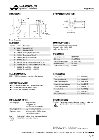
            DIMENSIONS                                           HYDRAULIC CONNECTION

                                   30                                                      17.8
                             A                     9.5                                T
                                                   5.5
                                                   MD= 5.2Nm
                                                       8                          A        B
                  85                                                           31                     21    32.5
                     E
                   45                                  45   46                        P
                                                       38
                                                                                    21.5
                                                                                      40.5
               20    50      10              70     40  60
             MD= 9.5Nm  MD= 5.2Nm                       MD=5.2Nm
                       4       64          64     15
                                     153
            E = Air bleed screw
            PARTS LIST                                           MANUAL OVERRIDE

              Position Article  Description                      Screw plug (HB0), no actuation possible
                  10 260.6...  Solenoid SIN45V                   Optionally: HB6, HN(K) or HR(K)
                                                                 → See data sheet 1.1-311
                     260.7...  Solenoid SIS45V
                  20 239.2033  Screw plug HB0 (incl. seal)
                  30 219.2001  Electric plug A (grey)            STANDARDS
                  35 219.2002  Electric plug B (black)            Mounting interface   ISO 4401-03
                  40 058.4215  Cover                              Solenoids            DIN VDE 0580
                                                                  Connection execution D  EN 175301 – 803
                  50 246.2160  Socket head screw M5 x 60 DIN 912  Protection class     EN 60 529
                  60 246.2117  Socket head screw M5 x 16 DIN 912
                                                                  Contamination efficiency  ISO 4406
                  70 160.2093  O-ring ID 9,25 x 1,78 (NBR)
                     160.6092  O-ring ID 9,25 x 1,78 (FKM)


            SEALING MATERIAL                                     ACCESSORIES
            NBR or FKM (Viton) as standard, choice in the type code  Fixing screws            Data sheet 1.0-60

                                                                  Threaded subplates          Data sheet 2.9-05
                                                                  Multi-station subplates     Data sheet 2.9-45
            SURFACE TREATMENT                                     Horizontal mounting blocks  Data sheet 2.9-85
             ◆  The valve body is painted with a two component paint  Technical explanations  Data sheet 1.0-100
             ◆  The solenoid and the cover are zinc coated
             ◆  The socket head screws are zinc coated            Hydraulic fluids            Data sheet 1.0-50
                                                                  Filtration                  Data sheet 1.0-50
                                                                  Relative duty factor        Data sheet 1.1-430


            INSTALLATION NOTES                                   COMMISSIONING
             Mounting type      Flange mounting                  Attention!  When commissioning, the valve must be vented under
                                4 fixing holes for                        pressure (max. two rotations of screw E).
                                socket head screws M5 x 45
             Mounting position  Any, preferably horizontal
             Tightening torque  Fixing screws M  = 5,2 Nm (screw
                                            D
                                quality 8.8, zinc coated)
            Note!    The length of the fixing screw depends on the base
                     material of the connection element.


                                                                 Wandfluh AG  Postfach  CH-3714 Frutigen
                                                                 Tel. +41 33 672 72 72  Fax +41 33 672 72 12  sales@wandfluh.com

                           www.wandfluh.com  Illustrations are not binding  Data subject to change  3/3  Edition: 17 26  1.11-10010 E
                                                                                                            Page 653
   648   649   650   651   652   653   654   655   656   657   658