
Page 528 - Softbound_Edition_19_en
P. 528
Poppet valve
Poppet valve cartridge Poppet valve
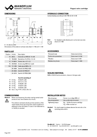
DIMENSIONS HYDRAULIC CONNECTION Solenoid operated poppet valve cartridge
Cavity drawing according to ISO 7789–33–01–0–98 ◆ solenoid operated M42 x 2
◆ pilot operated ISO 7789
110 M33 x 2 ◆ normally open and normally closed
s36 ◆ 2/2-way
◆ Q = 300 l/min
M33x2 ◆ p = 350 bar
max
94 60 (2) max
(2)
E
(1)
22.5 15 (1) DESCRIPTION APPLICATION
(1) Pilot operated 2/2-way solenoid poppet valve in screw-in cartridge Wandfluh solenoid operated poppet valve cartridges are used
12 17 18 10 18 19 40 13 30 construction for cavity according to ISO 7789. The AB and CB where tight closing functions are essential like leakage-free load
MD= 9Nm
60 Note! For detailed cavity drawing and cavity tools see data execution is closed in the energised position, the BA and BC execu- holding, clamping or gripping. For machining the cartridge cavity in
93 50 sheet 2.13-1005 tion in the de-energised position. In this, the main spool closes steel and aluminum blocks, cavity tools are available (hire or
147 practically leakage-free by means of the applied pressure. purchase). Please refer to the data sheets in register 2.13.
E = Air bleed screw
Dimensions of the solenoid coil see data sheet 1.1-183 and 1.1-184
PARTS LIST ACCESSORIES SYMBOL
Position Article Description Threaded body Data sheet 2.9-2xx „Normally open“ AB „Normally closed“ BA „Normally closed“ BC „Normally open“ CB
10 263.6... Solenoid coil MK.45 / 18 x 60 Technical explanations Data sheet 1.0-100 2 2 2 2
12 154.2603 Knurled nut Ex M18 x 1,5 x 18 Filtration Data sheet 1.0-50 a b a b a b a b
13 212.0013 Plastic disc rd 7 x 1,5 Relative duty factor Data sheet 1.1-430 1 1 1 1
15 239.2033 Screw plug HB0 (incl. seal)
110 111.1080 Cable gland M20 x 1,5
- 251.3009 Seal kit SV.PM33 NBR
- 251.3026 Seal kit SV.PM33 D1 TYPE CODE
- 251.3019 Seal kit SV.PM33 Z604 SEALING MATERIAL S V S PM42 - - / - #
NBR or FKM (Viton) as standard, choice in the type code Poppet valve
Seal kit consisting of Pilot operated
17 O-ring ID 25,07 x 2,62
18 O-ring ID 17,17 x 1,78 Solenoid, Super
19 O-ring ID 26,00 x 1,00 Screw-in cartridge M42 x 2
30 O-ring ID 23,81 x 2,62
40 O-ring ID 29,82 x 2,62 Designation of symbols acc. to table
60 Back. ring PTFE rd 24,5 x 29 x 1,4
Nominal voltage U N 12 VDC G12 115 VAC R115
24 VDC G24 230 VAC R230
COMMISSIONING INSTALLATION NOTES without coil X5
Attention! When commissioning, the valve must be vented under Mounting type Screw-in cartridge M33 x 2 Slip-on coil Metal housing, round W (only G12 and G24)
pressure (max. two rotations of screw E). Metal housing, square M
Mounting position Any, preferably horizontal
The solenoid coil must only be put into operation, if the Tightening torque M = 130 Nm Screw-in cartridge Connection execution
D
requirements of the operating instructions supplied are M = 9 Nm knurled nut Connector socket EN 175301-803 / ISO 4400 D
D
observed to their full extent. In case of non-observance, Connector socket AMP Junior-Timer J
no liability is assumed. Attention! For stack assembly please observe the remarks in the Connector Deutsch DT04-2P G
operating instructions
Sealing material NBR
FKM (Viton) D1
NBR 872 Z604
Armature tube with screw plug HB0
with manual override HB4,5 (only AB, CB)
Design index (subject to change)
Wandfluh AG Postfach CH-3714 Frutigen 1.11-2091
Tel. +41 33 672 72 72 Fax +41 33 672 72 12 sales@wandfluh.com
www.wandfluh.com Illustrations are not binding Data subject to change 4/4 Edition: 22 17 1.11-2085 E www.wandfluh.com Illustrations are not binding Data subject to change 1/4 Edition: 22 50 1.11-2091 E
Page 528