Page 232 - Softbound_Edition_19_en
P. 232

Solenoid operated spool valve
                                                                                Solenoid operated spool valve                                                                                                Solenoid operated spool valve


       DIMENSIONS                                                                                                                  Solenoid operated spool valve with soft switching
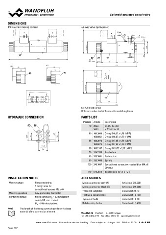
       4/3-way valve (spring centred)                      4/2-way valve (spring reset)                                                                                                 NG6
                                                                                                                                   Flange construction                                  ISO 4401-03
                  A                   B                                          A   130                                            ◆  4/3-way with spring centred mid position
                                                                                     140  E       9.5                               ◆  4/2-way with spring reset
                                                                                                  5.2   MD=5.2Nm                      Q  = 60 l/min
                                                                                                         6                          ◆  max
                                                              77                                                                    ◆  p  = 350 bar
                                                                                                                                       max
                                                               37                                          38
                                                                V =                                      32
                                                                                                                                   DESCRIPTION                                          APPLICATION
              10                                                                                  3      2.5                       Direct operated solenoid spool valve with 4 connections in 5 cham-  Normal solenoid spool valves switch very quickly. This can lead to
                            193                                   80   70    10
                                                                 MD= 5Nm   18    50        57      8                               ber design. With the solenoids deenergised, the spool is held in the   shocks in the hydraulic system which can cause mechanical wear
                                                                                                                                   center position by the spring (4/3), or switched back to the offset   and have a negative effect on operation. The soft switching valves
                                  HS1                                               133
         HF1                                                                                                                       position (4/2). The soft switching of the valve is achieved by means   slow down and dampen the switching movements which benefits
              43                        44
                30                       30                                                                                        of an optimum combination of the orifice and spool design. Precise   the system.  Optimum results can be achieved if all 4 connections
                      80                       90                           A                                                      spool  fit,  low  leakage,  long  service  life  time.  Spool  made  from   are connected and the valve is properly vented.


                                                                                                                                     h ardened steel, valve body from high quality hydraulic cast steel.
                                                                                                                                   Wide range of standard and special voltages.
                                                              77
                                                               35
                                                                N =
                                                                                                                                   SYMBOL
                                                                            10

                                                                                                                                                                                   AB1                        AB2
                                                                        15     53

                                                                                    133                                                                                                                    A  B
                                                           E = Air bleed screw                                                                                                   a    b                    a     b
                                                           Orifices in valve body influence the switching times                                                            a                b         a                 b
       HYDRAULIC CONNECTION                                PARTS LIST                                                                                                                                      P  T
                                                             Position Article  Description                                                     ACB                                 AC1                        CB2
                     50  55      14.5                            10 206.2...  V.E37 / 19 x 50                                                 A   B                                 A   B                  A  B

                               T                                    260.5...  N.S35 / 19 x 50                                        a    a     0   b      b               a     a                               b      b
                                         6.5                     50 160.2060  O-ring ID 6,07 x 1,78 (NBR)                                     P   T                                 P   T                  P  T
                      22.5    18   A  B     24                      160.6061  O-ring ID 6,07 x 1,78 (FKM)
                                                                 55 160.2076  O-ring ID 7,65 x 1,78 (NBR)                                      ADB                                 AD1                        DB2
                                P                                   160.6076  O-ring ID 7,65 x 1,78 (FKM)                                     A   B
                               15.4                                                                                                                                                 A   B                  A  B
                                24                               60 160.2187  O-ring ID 18,72 x 2,62 (NBR)                                a     0   b                            a                               b
                                                                 70 154.2700  Knurled nut                                            a                     b               a                                            b
                                                                 80 253.7001  Push-button                                                     P   T                                 P    T                 P  T

                                                                 90 253.7000  Spindle                                                          BEA                                 BE1                        EA2
                                                                130 246.1007  Socket head screw zinc-coated blue M4 x 6                       A   B                                 A   B                  A  B
                                                                            DIN84 A
                                                                                                                                           a          b                           a                                b
                                                                140 049.2040  Bonded seal ID 4,1 x 7,2 x 1                           a          0          b               a                                            b
       INSTALLATION NOTES                                  ACCESSORIES                                                                        P   T                                 P    T                 P  T
       Mounting type      Flange mounting                   Mating connector grey (A)    Article no. 219.2001                                  AFB                                 AF1                        FB2
                          3 fixing holes for                Mating connector black (B)   Article no. 219.2002                                 A   B                                 A   B                  A  B
                          socket head screws M5 x 40        Threaded subplates           Data sheet 2.9-12                                a     0   b                            a                               b
       Mounting position  Any, preferably horizontal        Technical explanations       Data sheet 1.0-100                          a                     b               a                                            b
       Tightening torque  Fixing screws M  = 5,2 Nm (screw                                                                                    P   T                                 P   T                  P  T
                                      D
                          quality 8.8, zinc coated)         Hydraulic fluids             Data sheet 1.0-50
                          M  = 5 Nm knurled nut             Relative duty factor         Data sheet 1.1-430
                            D
       Note!   The length of the fixing screw depends on the base
               material of the connection element.
                                                           Wandfluh AG  Postfach  CH-3714 Frutigen
                                                           Tel. +41 33 672 72 72  Fax +41 33 672 72 12  sales@wandfluh.com

                           www.wandfluh.com  Illustrations are not binding  Data subject to change  4/4  Edition: 22 09  1.4-23 E                      www.wandfluh.com  Illustrations are not binding  Data subject to change  1/5  Edition: 22 10  1.4-32 E
       Page 232
   227   228   229   230   231   232   233   234   235   236   237