
Page 218 - Softbound_Edition_19_en
P. 218
Solenoid operated spool valve
Solenoid operated spool valve Magnetschieberventil
ELECTRICAL CONNECTION Magnetschieberventil mit zusätzlicher
Handhebel-Betätigung NG6
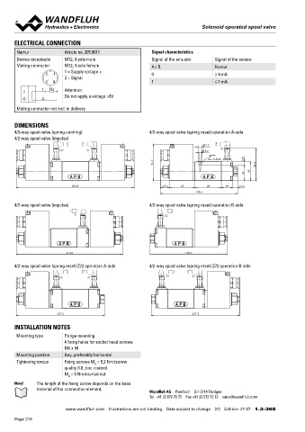
Namur Article no. 205.5011 Signal characteristics ISO 4401-03
Device receptacle M12, 4 pole male Signal of the actuator Signal of the sensor Flanschbauart
Mating connector M12, 4 pole female A / B Namur ◆ 4/3-Wege mit federzentrierter Mittelstellung x II 2 G Ex db IIC
1 = Supply voltage + ◆ Q = 80 l/min x II 2 D Ex tD A21 IP65
2 1 0 ≥ 4 mA max
2 = Signal ◆ p = 350 bar x I M2 Ex db I Mb
max
3 4 1 ≤ 1 mA
Class I Division 1
1 Rv Attention: Class I Zone 1
I +
Do not apply a voltage >9V
2 -
Mating connector not incl. in delivery
BESCHREIBUNG SINNBILD
DIMENSIONS Schieberventil gemäss Datenblatt 1.3-34 mit zusätzlicher Hand- Übersicht Kolbentypen siehe Datenblatt 1.3-34
4/3-way spool valve (spring centring) 4/2-way spool valve (spring reset) operation A-side hebel-Betätigung.
4/2-way spool valve (impulse)
Hinweis! Das Standardventil kann nicht nachgerüstet werden.
9.5
S1
S2 S1 5.2 A B
MD= 5.2Nm 8
94.3 83.3 a a 0 b b
41 49 P T
303.8 23.6 65 68 29 12.6 TYPENSCHLÜSSEL
198.6
WD Y F A06 - Z568 # 2
4/2-way spool valve (impulse) 4/2-way spool valve (spring reset) operation B-side Schieberventil, direktgesteuert
Ex-Schutz-Ausführung Ex d
S1 S2
Flanschbauart
Internationale Anschlussnorm ISO NG6
Restliche Typenbezeichnung gemäss Typenschlüssel Datenblatt 1.3-34
274.8 198.6 Handhebel
4/2-way spool valve (spring reset) Z72 operation A-side 4/2-way spool valve (spring reset) Z72 operation B-side Änderungs-Index (wird vom Werk eingesetzt)
1.3-37
S2 S1 S2 S1
ABMESSUNGEN ALLGEMEINE KENNGRÖSSEN
Gewicht WDYFA06 +1,0 kg
Hinweis! Weitere Kenngrössen, siehe Datenblatt 1.3-34
227.6 227.4
INSTALLATION NOTES
Mounting type Flange mounting 256.5
4 fixing holes for socket head screws OBERFLÄCHENBEHANDLUNGEN
M5 x 50 ◆ Der Flansch, das Gehäuse und der Hebel sind Zink-Nickel
Mounting position Any, preferably horizontal beschichtet
Tightening torque Fixing screws M = 5,2 Nm (screw
D
quality 8.8, zinc coated)
M = 5 Nm knurled nut 44.4
D 167.3 123
Note! The length of the fixing screw depends on the base 290.3
material of the connection element.
Wandfluh AG Postfach CH-3714 Frutigen Wandfluh AG Postfach CH-3714 Frutigen
Tel. +41 33 672 72 72 Fax +41 33 672 72 12 sales@wandfluh.com Tel. +41 33 672 72 72 Fax +41 33 672 72 12 sales@wandfluh.com
www.wandfluh.com Illustrations are not binding Data subject to change 2/2 Edition: 21 07 1.3-36 E www.wandfluh.com Abbildung unverbindlich Änderungen vorbehalten 1/1 Ausgabe: 19 38 1.3-37 D
Page 218