
Page 1291 - Softbound_Edition_19_en
P. 1291
21,22
25,30
X1
88
15
22.5
s 36
T(2)
20
17
106
(80)
146
X1
X3
88
P(1)
45 X2 X2 45 226 40 18 50 M 33x2 A(3) 60 80 80 70 P(1)
22.5
s 36 M 33x2 A(3) T(2)
Proportional flow control valves Proportional flow control valves
Proportional flow control valve
101 (80)
181
GENERAL SPECIFICATIONS SYMBOLS NOTE! Free-of-charge download of the «PASO»-software and the instruction
Description 3-way proportional flow control valve simplified detailed Detailed electrical characteristics and description of «DSV» manual for the «DSV» hydraulic valves as well as the operation instruc-
with integrated electronics electronics are shown on data sheet 1.13-76. tion CANopen eg.Profibus DP protocol with device profile DSP-408 for
Construction Screw-in cartridge for cavity acc. to ISO 7789 «DSV».
Operations Proportional solenoid, wet pin push type,
pressure tight
Mounting Screw-in thread M33x2 START-UP NOTE!
Ambient temperature -20…65 °C (typical) For DSV amplifiers as a rule no parameter settings by the customer are The mating connectors and the cable to adjust the settings
(The upper temperature limit is a guideline value for typical 1 3 1 3 required. The plugs have to be connected in accordance with the chap- are not part of the delivery. Refer to chapter
applications, in individual cases it may also be higher or lower. «Accessories».
The electronics of the valve limit the power in case of a too 2 ter «Pin assignment».
high electronics temperature. More detailed information can .
be obtained from the operating instructions «DSV».)
Mounting position any, preferably horizontal Additional information can be found on our website:
Fastening torque M = 80 Nm for screw-in cartridge 2 «www.wandfluh.com»
D
M D = 5 Nm for knurled nut
Weight m = 1,6 kg
Flow direction see symbol
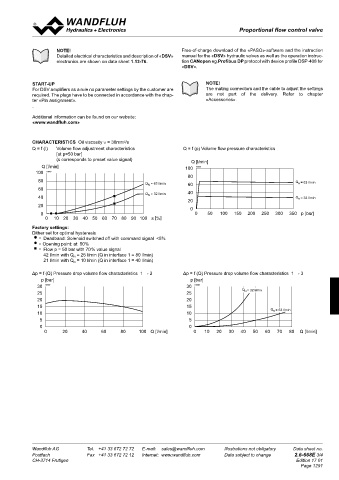
CHARACTERISTICS Oil viscosity υ = 30mm /s
2
CONNECTOR WIRING DIAGRAM Q = f (I) Volume flow adjustment characteristics Q = f (p) Volume flow pressure characteristics
Analog interface: [at p=50 bar]
(s corresponds to preset value signal)
HYDRAULIC SPECIFICATIONS Device receptacle (male) X1 Q [l/min]
Fluid Mineral oil, other fluid on request Q [l/min] 100 K0986
Contamination efficiency ISO 4406:1999, class 18/16/13 1 = Supply voltage + 100 K1140 80
(Required filtration grade β 6…10 ≥ 75) 8 9 1 2 = Supply voltage 0 VDC 80 Q = 63 l/min
see data sheet 1.0-50/2 3 = Stabilised output voltage Q = 63 l/min 60 N
N
Viscosity range 12 mm /s…320 mm /s 7 12 10 2 4 = Preset value voltage + 60 40
2
2
Fluid temperature -20…+70 °C 6 11 3 5 = Preset value voltage - 40 Q = 32 l/min Q = 32 l/min
N
Peak pressure p max = 350 bar 8 9 1 5 4 6 = Preset value current + 20 N
Nominal volume flow rates Q = 32 l/min, 63 l/min 7 12 10 2 7 = Preset value current - 20 0
1
N
8 9
Max. volume flow Q max = 100 l/min (1 → 2) 6 11 3 8 = Reserved for extensions 0 0 50 100 150 200 250 300 350 p [bar]
7 12 10 2
Min. volume flow Q min = 0,2 l/min 5 4 9 = Reserved for extensions 0 10 20 30 40 50 60 70 80 90 100 s [%]
6
11 3
Hysteresis ≤ 5 % 10 = Enable control (Digital input)
2 3 11 = Error signal (Digital output) Factory settings:
5 12 = Chassis 5 4 Dither set for optimal hysteresis
1 4 = Deadband: Solenoid switched off with command signal <5%
Preset value voltage (PIN 4/5) resp. current (PIN 6/7) are selected with
2 3 = Opening point: at 50%
ELECTRICAL SPECIFICATIONS 5 set-up and diagnosis software PASO. = Flow p = 50 bar with 70 % value signal
Protection class IP 67 acc. to EN 60 529 1 4 Factory setting: Voltage (0…+10 V), (PIN 4/5) 3 42 l/min with Q = 25 l/min (Q in interface 1 = 80 l/min)
2
with suitable connector and closed 8 9 1 5 21 l/min with Q N N = 10 l/min (Q in interface 1 = 40 l/min)
electronics housing 7 12 10 2 1 4
Supply voltage 12 VDC or 24 VDC Fieldbus interface:
11 3
6
1
Ramps adjustable Device receptacle supply (male) X1 Δp = f (Q) Pressure drop volume flow characteristics 1 → 2 Δp = f (Q) Pressure drop volume flow characteristics 1 → 3
2
1
2
4
5
Parameterisation via fieldbus or USB 5 p [bar] p [bar]
Interface USB (Mini B) for parameterisation 3 4 MAIN 3 4 30 K0987 30 K0988
with «PASO» 1 = Supply voltage + 25 25 Q = 32 l/min
N
2
under the closing screw of the housing cover, 1 2 1 2 = Reserved for extensions
Preset ex-works 5 2 3 3 = Supply voltage 0 VDC 20 20
Analog interface: 3 4 3 5 4 4 = Chassis 2 1 2 1 15 15
Device receptacle (male) M23, 12-poles 1 4 5 10 10 Q = 63 l/min
N
Mating connector Plug (female), M23, 12-poles 3 4 3 4
(not incl. in delivery) 2 3 5 5
Preset value signal Input voltage / current as well as signal range 5 0 0
can be set by software Device receptacle Device receptacle 0 20 40 60 80 100 Q [l/min] 0 10 20 30 40 50 60 70 80 Q [l/min]
1
4
CANopen (male) X3 Profibus (female) X3
Fieldbus interface: 2 3 CAN PROFIBUS
Device receptacle 5 1 = not connected 1 = VP
supply (male) M12, 4-poles 1 4 2 1 2 = not connected 2 3 2 = RxD / TxD - N
1
2
Mating connector Plug (female), M12, 4-poles 5 3 = CAN Gnd 5 3 = DGND
(not incl. in delivery) 3 4 3 4 1 4
Device receptacle 4 = CAN High 4 = RxD / TxD - P
CANopen (male) M12, 5-poles (acc. to DRP 303-1) 5 = CAN Low 5 = Shield
Mating connector Plug (female), M12, 5-poles
(not incl. in delivery)
Device receptacle Parameterisation interface (USB, Mini B) X2
Profibus (female) M12, 5-poles, B-coded (acc. to IEC 947-5-2) Under the closing screw of the housing cover
Mating connector Plug (male), M12, 5-poles, B-coded 2 3
(not incl. in delivery) 5
Preset value signal Fieldbus 1 4
Wandfluh AG Tel. +41 33 672 72 72 E-mail: sales@wandfluh.com Illustrations not obligatory Data sheet no. Wandfluh AG Tel. +41 33 672 72 72 E-mail: sales@wandfluh.com Illustrations not obligatory Data sheet no.
Postfach Fax +41 33 672 72 12 Internet: www.wandfluh.com Data subject to change 2.6-668E 2/4 Postfach Fax +41 33 672 72 12 Internet: www.wandfluh.com Data subject to change 2.6-668E 3/4
CH-3714 Frutigen Edition 17 01 CH-3714 Frutigen Edition 17 01
Page 1291