Page 1228 - Softbound_Edition_19_en
P. 1228

Proportional throttle valve                                                                                                  Proportional throttle valve
                                                                                    Proportional throttle valve


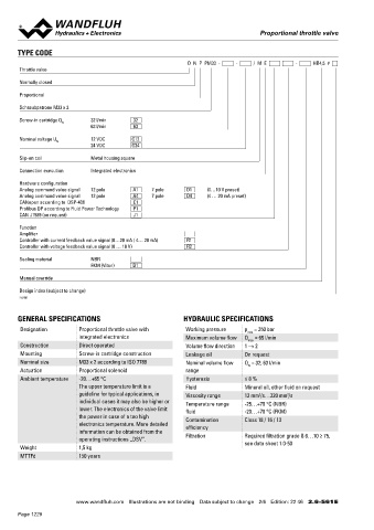
       TYPE CODE                                                                                                                   ELECTRICAL CONNECTION
                                                             D  N  P  PM33  -     -     /  M  E        -     HB4,5  #               X1                 Analog interface (Main)           X1                 Fieldbus interface (Main)
       Throttle valve
                                                                                                                                    Device receptacle  M23, 12 pole male                 Device receptacle  M12, 4 pole male
       Normally closed                                                                                                                                 1 = Supply voltage +                           2  1  1 = Supply voltage +
                                                                                                                                              8 9  1   2 = Supply voltage 0 VDC                       3 4   2 = Reserved for extentions
       Proportional                                                                                                                          7 12 10 2  3 = Stabilised output voltage                       3 = Supply voltage 0 VDC
                                                                                                                                             6  11 3
                                                                                                                                               5  4    4 = Command value signal voltage +                   4 = Chassis
       Schraubpatrone M33 x 2
                                                                                                                                                       5 = Command value signal voltage -
       Screw-in cartridge Q N    32 l/min   32                                                                                                         6 = Command value signal current +
                              63 l/min     63                                                                                                          7 = Command value signal current -
                                                                                                                                                       8 = Reserved for extentions
       Nominal voltage U N    12 VDC       G12                                                                                                         9 = Reserved for extentions       X2                 Parameterisation interface
                              24 VDC       G24
                                                                                                                                                       10 = Enable signal (Digital input)  USB, Mini B      Under the screw plug of the housing
       Slip-on coil           Metal housing square                                                                                                     11 = Error signal (Digital output)                   cover
                                                                                                                                                       12 = Chassis                                         Factory set
       Connection execution   Integrated electronics                                                                                Command value signal voltage (PIN 4/5) resp. current (PIN 6/7) are
                                                                                                                                    selected with parameterisation and diagnostics  software PASO.
       Hardware configuration
       Analog command value signal   12 pole   A1   7 pole   D1    (0…10 V preset)
       Analog command value signal   12 pole   A4   7 pole   D4    (4 … 20 mA preset)
       CANopen according to  DSP-408       C1                                                                                       X1                 Analog interface (Main)           X3                 Profibus interface according to IEC
       Profibus DP according to Fluid Power Technology   P1                                                                                            Connector DIN EN 175201 - 804                        947-5-2
       CAN J1939 (on request)              J1
                                                                                                                                    Device receptacle  7 pole male                       Device receptacle  M12, 5 pole female B-coded
       Function                                                                                                                                 A      A = Supply voltage +                           2 3   1 = VP
                                                                                                                                                                                                      5
       Amplifier                                                                                                                            F     B    B = Supply voltage 0 VDC                       1 4   2 = RxD / TxD - N
       Controller with current feedback value signal (0…20 mA / 4… 20 mA)   R1                                                                  G      C = Not connected                                    3 = DGND
       Controller with voltage feedback value signal (0 … 10 V)       R2                                                                    E   D  C   D = Command value signal +                           4 = RxD / TxD - P
                                                                                                                                                       E = Command value signal -                           5 = Shield
       Sealing material       NBR
                              FKM (Viton)   D1                                                                                                         F = Not connected
                                                                                                                                                       G = Chassis
       Manual override
                                                                                                                                    Command value signal: current (D4) or voltage (D2) to specify
                                                                                                                                    when placing the order
       Design index (subject to change)
       2.6-561
                                                                                                                                    X3                 CANopen interface according to DRP   X4 (controller only)  Feedback value interface (sensor)
       GENERAL SPECIFICATIONS                              HYDRAULIC SPECIFICATIONS                                                                    303-1                             Device receptacle  M12, 5 pole female

       Designation        Proportional throttle valve with   Working pressure  p  = 350 bar                                         Device receptacle  M12, 5 pole male                               2 3   1 = Supply voltage (output) +
                                                                                max
                                                                                                                                                                                                      5
                          integrated electronics            Maximum volume flow  Q  = 65 l/min                                                   2 1   1 = Not connected                              1 4   2 = Feedback value signal +
                                                                                                                                                  5
                                                                                max
       Construction       Direct operated                   Volume flow direction  1 → 2                                                         3 4   2 = Not connected                                    3 = Supply voltage 0 VDC
                                                                                                                                                                                                            4 = Not connected
                                                                                                                                                       3 = CAN Gnd
       Mounting           Screw-in cartridge construction   Leakage oil        On request                                                              4 = CAN High                                         5 = Stabilised output voltage
       Nominal size       M33 x 2 according to ISO 7789     Nominal volume flow   Q  = 32; 63 l/min                                                    5 = CAN Low
                                                                                N
       Actuation          Proportional solenoid             range                                                                                                                        Feedback value signal: current (R1) or voltage (R2) to specify
                                                                                                                                                                                         when placing the order
       Ambient temperature  -20…+65 °C                      Hysteresis         ≤ 8 %
                          The upper temperature limit is a   Fluid             Mineral oil, other fluid on request                 Note!    The mating connector is not included in the delivery
                          guideline for typical applications, in   Viscosity range  12 mm /s…320 mm /s
                                                                                            2
                                                                                   2
                          individual cases it may also be higher or   Temperature range   -25…+70 °C (NBR)
                          lower. The electronics of the valve limit   fluid    -20…+70 °C (FKM)
                          the power in case of a too high   Contamination      Class 18 / 16 / 13
                          electronics temperature. More detailed   efficiency
                          information can be obtained from the   Filtration    Required filtration grade ß 6…10 ≥ 75,
                          operating instructions „DSV”.                        see data sheet 1.0-50
       Weight             1,5 kg
       MTTFd              150 years


                         www.wandfluh.com  Illustrations are not binding  Data subject to change  2/6  Edition: 22 46  2.6-561 E                      www.wandfluh.com  Illustrations are not binding  Data subject to change  3/6  Edition: 22 46  2.6-561 E
       Page 1228
   1223   1224   1225   1226   1227   1228   1229   1230   1231   1232   1233