
Page 1208 - Softbound_Edition_19_en
P. 1208
70
60
10 18
50
M 18 X 1.5
20
s 24
68
15
(2)
(1)
30 66.3 29.4 Proportional throttle valve
Proportional throttle valve
95.7 Proportional throttle valves
SYMBOLS Proportional throttle cartridge
◆ direct operated M22 x 1,5
Normally closed Normally open
◆ Q = 32 l/min ISO 7789
max
2 2 ◆ Q N max = 25 l/min
◆ p = 350 bar
max
1 1
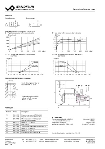
CHARACTERISTICS Oil viscosity υ = 30 mm /s
2
Q = f (p) Leakage volume flow characteristics Q = f (p) Volume flow pressure characteristics DESCRIPTION APPLICATION
L
Q [cm /min] Q [l/min] Direct operated proportional throttle valve in screw-in cartridge Proportional throttle valves are suitable for smooth control of
3
200 K0140 15 K0143 construction for cavity according to ISO 7789. With the solenoid movements in stationary or mobile systems. The screw-in
12.5 Q = 6.3 l/min
150 N deenergised, the control spool is held in the closed position (DN) or cartridge is perfectly suitable for installation in control blocks
10 open position (DO) by a spring. The change of the electric current is and is installed in sandwich- (vertical stacked systems) and in
100 7.5 Q = 4 l/min followed by a proportional volume flow change. Very sensitive flange plates (corresponding data sheets in this register). For
N
5
50 opening and closing characteristics and low hysteresis are charac- machining the cartridge cavity in steel and aluminum blocks,
2.5 teristics of these valves. For the control, Wandfluh proportional cavity tools are available (hire or purchase). Please refer to the
0 0 amplifiers are available (see register 1.13). data sheets in register 2.13.
0 50 100 150 200 250 p [bar] 0 50 100 150 200 250 p [bar]
Q = f (I) Volume flow adjustment characteristics Q = f (I) Volume flow adjustment characteristics
DNPPM18 DOPPM18
Q [l/min] Q [l/min] SYMBOL
8 K0142 8 K0141 „normally closed” DN „normally open” DO
7 Q = 6.3 l/min 7 Q = 6.3 l/min 2 2
N
N
6 6
5 Q = 4 l/min 5 Q = 4 l/min
N
N
4 4
3 3
2 2 1 1
1 1
0 0
0 10 20 30 40 50 60 70 80 90 100 l [%] 0 10 20 30 40 50 60 70 80 90 100 l [%] TYPE CODE
DIMENSIONS / SECTIONAL DRAWINGS D P PM22 - - / - #
Throttle valve
M18x1,5
Cavity drawing according to Normally closed N
ISO 7789–18–01–0–98 10 18 50 70 60 Normally open O
Proportional
(2)
20 M 18 X 1.5
68 s 24 Screw-in cartridge M22 x 1,5
15
(1) (2) Nominal volume flow rate Q 3,5 l/min 3,5
For detailed cavity drawing N
and cavity tools see data (1) 6,3 l/min 6,3
(1) sheet 2.13-1002. 10 l/min 10
25 l/min 25
30 66.3 29.4 Nominal voltage U N 12 VDC G12
95.7 24 VDC G24
PARTS LIST without coil X5
Position Article Description Slip-on coil Metal housing round W
Metal housing square M
10 256.2453 Proportional solenoid PI29V-G24
256.2418 Proportional solenoid PI29V-G12 ACCESSORIES 2 2 Connection execution Connector socket EN 175301-803/ISO 4400 D
15 253.8000 Mounted screw with integrated Flange-/sandwich plate NG3-Mini Data sheet 2.6-700 Connector socket AMP Junior - Timer J
manual override HB4,5 Line mount body Data sheet 2.9-205 Connector Deutsch DT04-2P G
18 160.2120 O-ring ID 12,42x1,78 Proportional amplifi er Register 1.13
1
1
20 219.2002 Plug (black) Mating connector EN 175301-803 Article Nr. 219.2002 Sealing material NBR
30 246.0146 Socket head cap screw M3x45 DIN912 FKM (Viton) D1
50 160.2156 O-ring ID 15,60x1,78 Armature tube with screw plug HB0
60 160.2111 O-ring ID 11,11x1,78 with manual override HB4,5
70 049.3156 Back up ring RD 12,1x15x1,4 Technical explanation see data sheet 1.0-100
Design index (subject to change)
2.6-531
Wandfluh AG Tel. +41 33 672 72 72 E-mail: sales@wandfluh.com Illustrations not obligatory Data sheet no.
Postfach Fax +41 33 672 72 12 Internet: www.wandfluh.com Data subject to change 2.6-510E 2/2 www.wandfluh.com Illustrations are not binding Data subject to change 1/4 Edition: 22 50 2.6-531 E
CH-3714 Frutigen Edition 05 06
Page 1208